
Standing wave tube installation mechanical device for sound intensity measurement instrument calibration device

A technology for calibrating devices and mechanical devices, applied to measuring devices, measuring ultrasonic/sonic/infrasonic waves, instruments, etc. It can solve the problems of difficult adjustment of installation holes, large spacing, and unfixed relative positions of standing wave tubes, etc., to improve repeatability , reduce workload, and reduce the effect of calibration error sources

Active Publication Date: 2013-12-11
BEIJING AEROSPACE INST FOR METROLOGY & MEASUREMENT TECH +1
View PDF4 Cites 4 Cited by
  • Summary
  • Abstract
  • Description
  • Claims
  • Application Information

AI Technical Summary

Problems solved by technology

The existing two standing wave tubes adopt a split structure. The relative positions of the two symmetrically installed standing wave tubes are not fixed, and the distance between them is too large. It is difficult to adjust the installation holes to be parallel to the axis, which makes it difficult to install the sound intensity probe of the sound intensity measuring instrument. in place

Method used


Image

  • Standing wave tube installation mechanical device for sound intensity measurement instrument calibration device
  • Standing wave tube installation mechanical device for sound intensity measurement instrument calibration device
  • Standing wave tube installation mechanical device for sound intensity measurement instrument calibration device

Examples


Embodiment Construction

[0013] A standing wave tube installation mechanical device for a sound intensity measuring instrument calibration device according to the present invention will be further described below in conjunction with the accompanying drawings and specific embodiments.

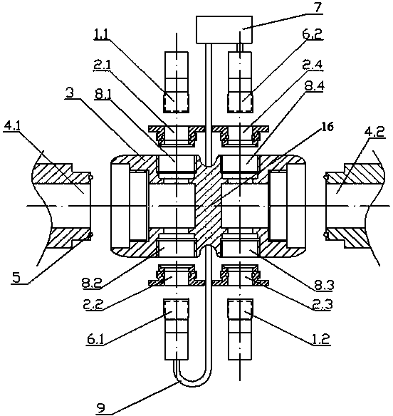
[0014] Such as figure 2 As shown, the ends of the two standing wave tubes 4.1 and 4.2 are designed as an integral structure in the calibrating device for the sound intensity measuring instrument according to the present invention. The outer diameter of standing wave tube 1 4.1 and standing wave tube 2 4.2 is 47mm, and the inner diameter is 25mm. The outer diameter of the connector 3 is 57 mm, the length is 105 mm, and the thickness of the connection interval 16 at the inner center of the connector 3 is 15 to 20 mm (for example, 15 mm, 17 mm or 20 mm); the center of the outer surface of the connection interval 16 has an annular concave groove.

[0015] Both sides of the connector 3 are threadedly connected to the firs...


PUM

PropertyMeasurementUnit
Thicknessaaaaaaaaaa

Abstract

The invention provides a standing wave tube installation mechanical device for a sound intensity measurement instrument calibration device. The two sides of a connector of the device are connected with a first standing wave tube and a second standing wave tube respectively in a threaded mode. A first microphone installation hole and a second microphone installation hole are vertically and symmetrically formed in the portion, of the position of the first standing wave tube, on a connector body. A fourth microphone installation hole and a third microphone installation hole are vertically and symmetrically formed in the portion, of the position of the second standing wave tube, on the connector body. The first microphone installation hole is connected with a first standard microphone. The third microphone installation hole is connected with a second standard microphone. The second microphone installation hole is connected with a first sound intensity probe microphone. The fourth microphone installation hole is connected with a second sound intensity probe microphone. According to the standing wave tube installation mechanical device for the sound intensity measurement instrument calibration device, the sound reduction index is guaranteed, meanwhile, the installation positions of the sound intensity probe microphones are fixed, the work load of position adjustment is reduced, the repeatability of installation is improved, the calibration errors caused by unparallel axes of the installation holes are reduced.

Description

technical field [0001] The invention relates to an acoustic measurement device, in particular to a standing wave tube installation mechanical device used for a calibration device of a sound intensity measuring instrument. Background technique [0002] There are two calibration methods for the calibration of sound intensity measuring instruments: free field method and standing wave field double resonance acoustic wave amplitude and phase control. The existing standing wave tube method sound intensity measuring instrument calibration device such as figure 1 shown. The existing two standing wave tubes adopt a split structure. The relative positions of the two symmetrically installed standing wave tubes are not fixed, and the distance between them is too large. It is difficult to adjust the installation holes to be parallel to the axis, which makes it difficult to install the sound intensity probe of the sound intensity measuring instrument. in place. Contents of the inventi...

Claims


Application Information

Patent Timeline
IPC IPC(8): G01H17/00
Inventor 闫磊杨晓伟朱刚刘鑫缪寅宵李强裴亚鹏张大有咸宝金
Owner BEIJING AEROSPACE INST FOR METROLOGY & MEASUREMENT TECH
Features
  • Generate Ideas
  • Intellectual Property
  • Life Sciences
  • Materials
  • Tech Scout
  • Unparalleled Data Quality
  • Higher Quality Content
  • 60% Fewer Hallucinations
Learn More