Double-layer thin film residual stress testing structure

A technology for testing structures and residual stress, applied in the measurement of permanent deformation force through measurement gauges, etc., can solve problems such as actual performance design performance deviation, influence, initial deformation of structures, etc., to achieve stable test process and test parameter values, and test The method is simple and the test equipment requires less effect

Inactive Publication Date: 2013-12-11
SOUTHEAST UNIV
View PDF4 Cites 7 Cited by
  • Summary
  • Abstract
  • Description
  • Claims
  • Application Information

AI Technical Summary

Problems solved by technology

When the MEMS structure is released, the residual stress will cause the initial deformation of the structure or have an impact on other material parameters, resulting in the deviation of the actual performance from the design performance

Method used


Image

  • Double-layer thin film residual stress testing structure
  • Double-layer thin film residual stress testing structure
  • Double-layer thin film residual stress testing structure

Examples


Embodiment Construction

[0028] The following description is merely exemplary in nature and not intended to limit the disclosure, application or use. It should be understood that throughout the drawings, corresponding reference numerals indicate like or corresponding parts and features.

[0029] Attached below Figure 1~4 The present invention will be further described.

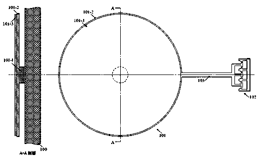
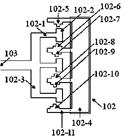
[0030] The present invention provides a test structure for measuring the residual stress of a double-layer film. The test structure consists of three parts: a disc 101; a projected vernier 102; and a straight beam 103 connecting the double-layer film disc 101 and the projected vernier 102.

[0031] The disc 101 includes three concentric circular structures: a cylinder 101-1, a first layer of film material 101-2 and a second layer of film material 101-3, and the film materials 101-2, 101-3 are both circular The second layer of film material 101-3 covers the first layer of film material 101-2. In order to meet the requirements of pro...


PUM


Abstract

The invention brings forward a double-layer thin film material residual stress testing structure. A measuring unit is a first layer thin film disc structure which is supported by a circular cylinder. The surface of the first layer thin film disc is covered with another layer thin film material so that a double-layer thin film disc structure is formed. The diameter direction of the edge of the first layer thin film disc stretches out so that a straight beam is formed. The tail end of the straight beam is provided with a projection vernier. The simple double-layer thin film disc structure is adopted and the projection vernier is combined cooperatively so that residual stress of an MEMS common thin film material can be obtained. Besides, residual stress test of each layer thin film under the condition of more layers of thin film material can be popularized, and a measuring method and a calculation method of parameter extraction are quite simple.

Description

technical field [0001] The invention provides a residual stress test structure for double-layer film materials. It belongs to the technical field of microelectromechanical system (MEMS) material parameter testing. Background technique [0002] The performance of microelectromechanical devices is closely related to material parameters. Due to the influence of processing, some material parameters will change. These uncertain factors caused by processing technology will make device design and performance prediction uncertain and unstable. Case. The purpose of material parameter testing is to be able to measure the material parameters of MEMS devices manufactured by a specific process in real time, monitor the stability of the process, and feed back the parameters to the designer so that the design can be corrected. Therefore, testing without leaving the processing environment and using general-purpose equipment has become a necessary means of process monitoring. [0003] Thi...

Claims


Application Information

Patent Timeline
Patent Type & Authority Applications(China)
IPC IPC(8): G01L1/06
Inventor 李伟华王雷张晓强周再发刘海韵孙超
Owner SOUTHEAST UNIV
Why Eureka
Try Eureka