Mixed type connector plug

A connector plug and mixed-type technology, applied in the field of mixed-type connector plugs, can solve the problems of increased product cost, wear and tear, wasting time, etc., and achieve the effects of high positioning accuracy, good anti-vibration, and convenient product installation.

Active Publication Date: 2013-12-11
SHANGHAI AEROSPACE SCI & IND ELECTRIC APPLIANCE RES INST
View PDF6 Cites 7 Cited by
  • Summary
  • Abstract
  • Description
  • Claims
  • Application Information

AI Technical Summary

Problems solved by technology

[0003] Usually, in order to minimize the mutual interference between different types of signals, RF connectors, power connectors, digital connectors, and optical fiber connectors are mostly arranged separately and dispersedly, and the connectors are generally assembled by screws, that is, through The locking of the screw on the shell flange fixes the connector to the panel or circuit board in the system. This method has high installation reliability and is widely used. However, as the demand for transmission signal channels continues to increase, installation Under the condition that the space is constant or gradually reduced, the defects of this installation method are very prominent. Not only does the installation waste a lot of time, but also the limited space cannot accommodate the mounting flanges of multiple connectors.
In addition, when multiple connectors are used at the same time and are located on the same installation plane, the position between the connectors must be guaranteed by the high-precision PCB board. Large butt joint force, severe wear and other phenomena
[0004] In addition, as the signal transmission rate continues to increase, the influence of electromagnetic interference from the outside world and radiation interference between boards and electronic components inside the equipment on the transmission line is becoming more and more obvious. However, in the limited chassis space In the interior, the spacing between the sub-boards, between the functional connectors and the contact pins inside the connectors is becoming narrower and narrower. Therefore, how to effectively realize the Connector reinforcement, shielding and other functions are currently a challenge faced by various connector manufacturers

Method used


Image

  • Mixed type connector plug
  • Mixed type connector plug
  • Mixed type connector plug

Examples


Embodiment

[0022] The embodiments of the present invention will be further described in detail below in conjunction with the accompanying drawings.

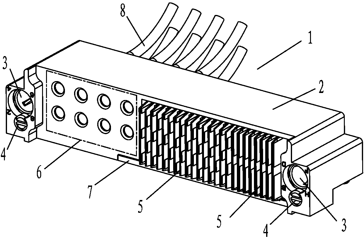
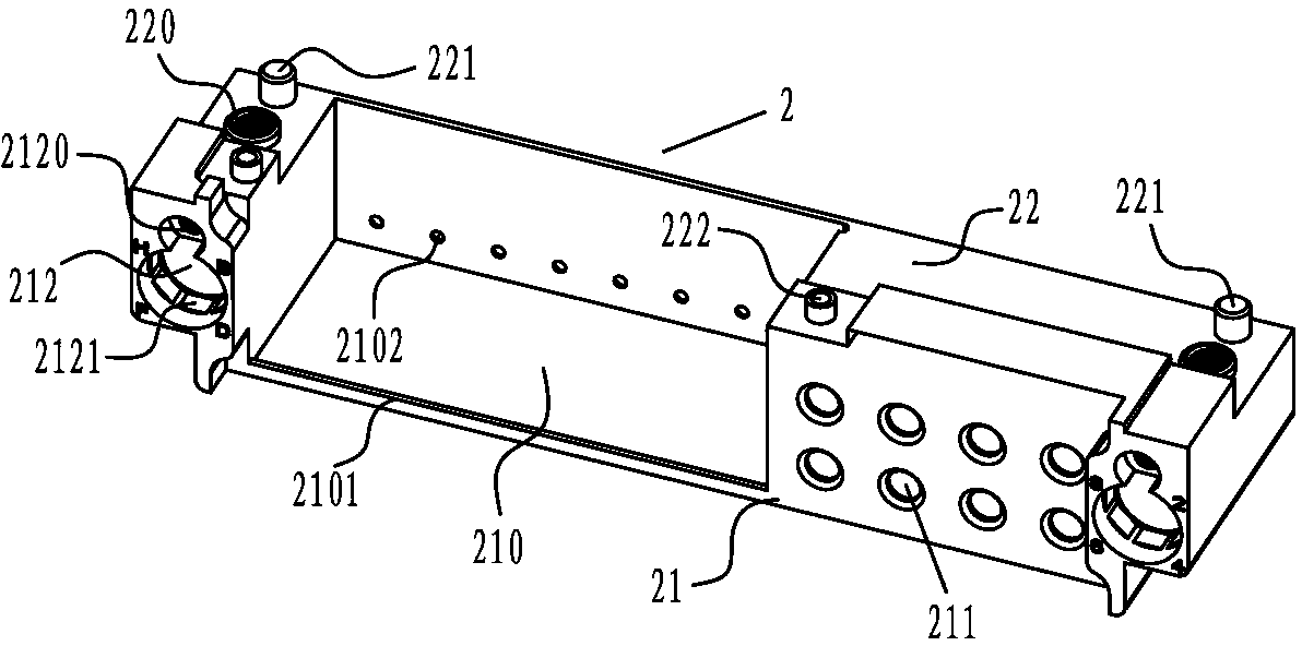
[0023] refer to figure 1 , the present invention 1 is composed of a housing part, a guide part, a module part and a functional terminal part, wherein the housing part includes: a fixed cover 2 formed by machining and a clamping plate 7 for fixing; The guide part includes a locking screw 4 for fixing and a guide ring 3 for positioning and guiding. They are fixed on both ends of the fixed cover 2 and located on both sides of the connector module, which can realize the connection between the connector module and the guide. High relative position relationship between components; the module part includes: digital module 5 and functional module 6, wherein the digital module 5 is fixed in the inner cavity of the fixed cover 2 through the clamp plate 7; the functional module 6 includes reinforcement units and accessories unit, the reinforcement un...


PUM


Abstract

The invention discloses a mixed type connector plug. The plug comprises a housing portion, a guide portion, a connector module portion and a function terminal portion, wherein the housing portion is composed of a fixed cover and a clamping plate; the connector module portion comprises a digital module and a function module; the function module comprises a reinforcing unit and an accessory unit; the reinforcing unit and the fixed cover are designed to form one body; the digital module is installed in the inner cavity of the fixed cover in a clamping manner and is limited by the clamping plate; the guide portion is arranged at the two ends of the fixed cover; and the function terminal portion is installed in the reinforcing unit of the function module through the accessory unit of the function module in a clamping manner. By using the mixed type connector plug, a radio frequency line, a fiber line, a power line and a digit line can be connected, the positioning precision is high, the product installation is convenient, and the mixed type connector plug also has the advantages of electromagnetic shielding, guiding adjustment, wrong plugging prevention, good mechanical properties such as vibration resistance, impact resistance and the like, and anti-electromagnetic interference capability.

Description

technical field [0001] The invention relates to the technical field of electrical connectors, in particular to a mixed-type connector plug, which is mainly used on the edge of a sub-board in a backplane architecture system for the transmission of various signals or power sources. Background technique [0002] In the backplane architecture connection system, with the continuous increase of signal transmission rate and transmission frequency, the corresponding reduction in the size of a single machine and the increasing demand for radio frequency lines, power lines, digital lines, and optical fiber lines in the system and many other factors , put forward new requirements and challenges for the installation and arrangement of various types of connectors in the system. [0003] Usually, in order to minimize the mutual interference between different types of signals, RF connectors, power connectors, digital connectors, and optical fiber connectors are mostly arranged separately a...

Claims


Application Information

Patent Timeline
Patent Type & Authority Applications(China)
IPC IPC(8): H01R27/00H01R13/514H01R13/631H01R13/6581H01R13/533
Inventor 肖顺群曹永泉李欣兴
Owner SHANGHAI AEROSPACE SCI & IND ELECTRIC APPLIANCE RES INST
Why Eureka
Try Eureka