
Wireless transceiver and logic control method thereof

A wireless transceiver and control line technology, applied in the field of Internet of Things communication, can solve the problem of general transmission power, etc., and achieve the effect of simple and compact structure, less modules used, and low cost

Active Publication Date: 2015-12-09
佛山市赛瑞通讯有限公司
View PDF5 Cites 0 Cited by
  • Summary
  • Abstract
  • Description
  • Claims
  • Application Information

AI Technical Summary

Problems solved by technology

The above scheme facilitates the realization of the game, but the transmission power is average, usually only 10mW

Method used


Image

  • Wireless transceiver and logic control method thereof
  • Wireless transceiver and logic control method thereof
  • Wireless transceiver and logic control method thereof

Examples


Embodiment 1

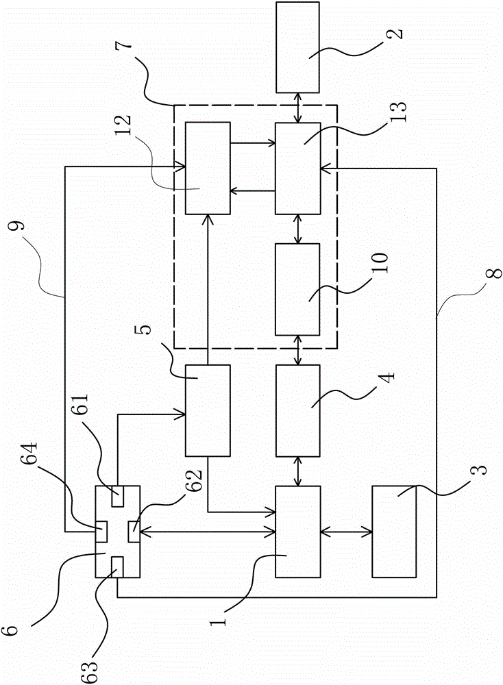
[0031] Such as figure 1 As shown, the wireless transceiver includes an RF communication chip 1 and an antenna 2 . The antenna 2 is any one of a spring antenna, an SMA rotatable antenna, a UFL rotatable antenna, a rod antenna, a whip antenna, and a PCB antenna. In this embodiment, the spring antenna 2 is directly welded, and the frequency of the antenna 2 is determined according to the analog working frequency band. A crystal oscillator circuit 3 , a balun circuit 4 , a power processing circuit 5 and a user interface module 6 are connected to the RF communication chip 1 . The transceiver also includes a signal processing and switching unit 7, the user interface module 6 includes a power interface 61, an SPI interface 62, a REN control interface 63 and a TEN control interface 64, and the power interface 61 is connected to the power processing circuit 5 , the SPI interface 62 is connected to the RF communication chip 1, the REN control interface 63 is connected to the signal pr...

Embodiment 2

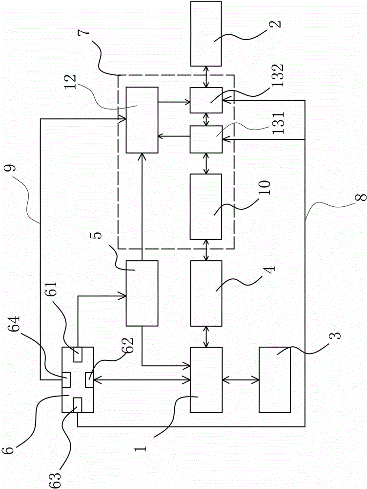
[0043] Such as figure 2 As shown, in this embodiment, the RF switching circuit 13 includes a first RF switching switch 131 connected to the low-pass filter circuit 10 and a second RF switching switch 132 connected to the antenna 2, the first RF switching switch 131 and the second RF switching switch 132 The two RF switches 132 are connected to each other and the RF power amplifier circuit 12 is connected to the first RF switch 131 and the second RF switch 132, and the first RF switch 131 and the second RF switch 132 are connected through the RXEN control line 8 It is connected with the REN control interface 63 . The rest are similar to those in Example 1, and will not be described in detail herein.

Embodiment 3

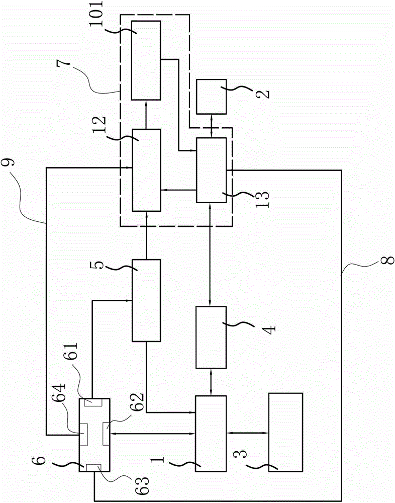
[0045] Such as image 3 As shown, in this embodiment, the signal processing and switching unit 7 includes a first low-pass filter circuit 101, an RF power amplifier circuit 12 and an RF switching circuit 13, and the RF power amplifier circuit 12 communicates with the RF power amplifier circuit 9 through the TXEN control line 9. The TEN control interface 64 is connected, the RF switching circuit 13 is connected to the REN control interface 63 through the RXEN control line 8, the power processing circuit 5 is connected to the RF power amplifier circuit 12 and the RF power amplifier circuit 12 and The RF switching circuits 13 are connected to each other, the balun circuit 4 is connected to the RF switching circuit 13, the first low-pass filter circuit 101 is connected between the RF power amplifier circuit 12 and the RF switching circuit 13, and the antenna 2 Connected to the RF switching circuit 13. The rest are similar to those in Example 1, and will not be described in detail...


PUM


Abstract

The invention belongs to the technical field of communication of the Internet of Things and relates to a wireless transceiver and a control method thereof. The wireless transceiver and the logic control method thereof solve the technical problems that existing design is not reasonable and the like. A crystal oscillator circuit, a Balun circuit, a power processing circuit and a user interface module are connected to an RF communication chip. The user interface module comprises a power interface, an SPI interface, an REN control interface and a TEN control interface. The power interface is connected with the power processing circuit, the SPI interface is connected with the RF communication chip, the REN control interface is connected with a signal processing and switching unit through an RXEN control line, and the TEN control interface is connected with the signal processing and switching unit through a TXEN control line. The power processing circuit and the Balun circuit are respectively connected with the signal processing and switching unit, and an antenna is connected to the signal processing and switching unit. The wireless transceiver and the control method thereof have the advantages that the structure is simple and compact, the number of used modules is small, and cost is low; the transmission power is high, the transmission frequency can be adjusted, and using of the wireless transceiver and the logic control method thereof is flexible and convenient.

Description

technical field [0001] The invention belongs to the technical field of Internet of Things communication, and relates to wireless transmission equipment, in particular to a wireless transceiver and a logic control method thereof. Background technique [0002] A wireless transceiver is a device that receives and sends wireless signals. Today, with the development of electronic information technology, it has become popular in people's daily life. Wireless transceivers are widely used in industries such as the Internet of Things. Traditional wireless transceivers have complex structures, many modules, high prices, and average transmission power, usually only 10mW, which is not suitable for the development trend of the Internet of Things industry. [0003] For this reason, people have carried out long-term exploration, put forward various solutions. For example, a Chinese patent document discloses a wireless transceiver system [Application No.: 200610034228.8], which includes a...

Claims


Application Information

Patent Timeline
Patent Type & Authority Patents(China)
IPC IPC(8): H04B1/401
Inventor 贾灵孙昭德郑淑军马玉龙韩利群
Owner 佛山市赛瑞通讯有限公司
Learn More