Electrodialysis unit for water treatment

A technology of electrodialysis and water flow, applied in the field of water treatment, can solve serious problems of the environment, industry and human health

Inactive Publication Date: 2013-12-11
海洋保护公司
View PDF4 Cites 5 Cited by
  • Summary
  • Abstract
  • Description
  • Claims
  • Application Information

AI Technical Summary

Problems solved by technology

There may be no natural predators of these species at the point of discharge, and they can coloniz...

Method used


Image

  • Electrodialysis unit for water treatment
  • Electrodialysis unit for water treatment
  • Electrodialysis unit for water treatment

Examples


Embodiment Construction

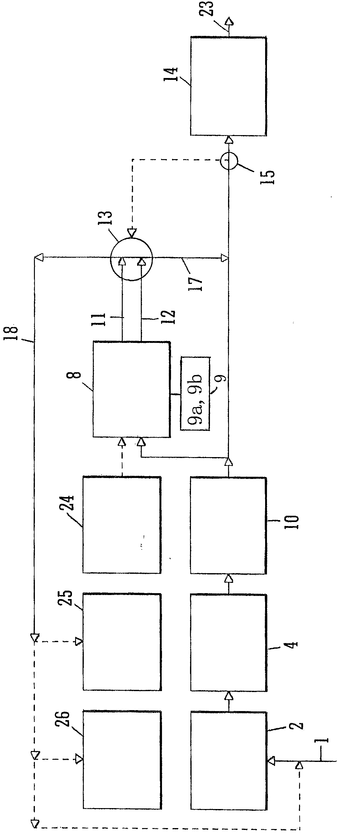
[0109] figure 1 The arrangement uses electrodialysis units in ballast water treatment systems, but recognizes that there are other applications where electrodialysis units are preferred and that electrodialysis units can be tailored to suit different requirements. In particular, it should be understood that the electrodialysis unit described herein may be used for ballast water treatment, or for other water treatment applications, without the need for a combination figure 1 Other treatment types shown in exemplary arrangements.

[0110] therefore, figure 1 A ballast water treatment system comprising an electrodialysis unit 8 is illustrated. In this example, the water is filtered and then treated through the cavitation unit 10 , the gas injection unit 14 and the electrodialysis unit 8 . This series of treatments destroys and kills organisms in the water. As well as affecting organisms in the water, the nitrogen added to the water at the injection device 14 reduces the disso...


PUM


Abstract

An electrodialysis unit 8 comprises a cathode 68, an anode 70, a membrane 71 between the cathode 68 and the anode 70, a cathode flow path 72 for water flow along the membrane 71 on the cathode side, an anode flow path 74 for water flow along the membrane 71 on the anode side, and a reaction zone formed between the membrane 71 and the cathode 68 where the cathode 68 faces the anode 70, wherein the cathode flow path 72 is arranged for laminar flow in the reaction zone and wherein the electrodialysis unit 8 comprises flow conditioning elements 64 arranged to promote laminar flow in the incoming water flow to the cathode flow path 72.

Description

technical field [0001] The present invention relates to the treatment of water by electrodialysis, such as treatment to kill microorganisms, preferably sea water, such as ballast water treatment. Background technique [0002] Ballast water is water carried by a ship in ballast tanks or sometimes in other suitable spaces such as cargo or oil tanks. It is pumped into the tank at the water "donor" location to compensate for changes in the center of gravity as cargo and / or fuel is unloaded / consumed, and thus maintain stability. Proper ballasting is essential from a structural point of view and also for performance reasons in order to ensure proper propeller and rudder immersion, proper bridge considerations and to maintain desired vessel movement and handling characteristics. Ballast water is transported to a water "holding" location, typically where the vessel is loaded with cargo, potentially outside the biogeographical region of the ballast water source. Ballast water can b...

Claims


Application Information

Patent Timeline
IPC IPC(8): C02F1/469B01D61/44B01D61/50B01D61/52C02F103/08
CPCB01D61/44B01D61/50B01D61/54B01D63/085B01D2311/04B01D2311/10B01D2311/103B01D2311/2649B01D2311/2661B01D2313/105C02F1/4693C02F2103/008C02F2103/08C02F2201/4611C02F2301/022B01D61/422B01D61/46C02F1/469B01D61/52B01D2313/08C02F2201/46115
Inventor A·B·安德森
Owner 海洋保护公司
Why Eureka
Try Eureka