
Core rod locking-type safety syringe

A safety syringe and locking technology, applied in the field of medical devices, can solve problems such as accidental injury, waste of manpower and funds, unreasonable design structure, etc., to achieve the effect of ensuring automated mass production, avoiding accidental injury, and reasonable design structure

Inactive Publication Date: 2013-12-18
常州市康福莱医疗用品有限公司
View PDF5 Cites 1 Cited by
  • Summary
  • Abstract
  • Description
  • Claims
  • Application Information

AI Technical Summary

Problems solved by technology

[0004] Some of the existing safety syringes are not equipped with a stem locking mechanism. After the syringe is completed, the plunger can still be pushed forward into the cylinder or pulled out from the rear end of the cylinder, resulting in accidental injury. Although some safety syringes have been designed Considering the necessity of the core rod locking mechanism, its design structure is unreasonable. Although the core rod can be firmly locked, it cannot be automatically assembled at the rear, which directly leads to the inability to automate mass production and waste a lot of manpower and funds.

Method used


Image

  • Core rod locking-type safety syringe
  • Core rod locking-type safety syringe
  • Core rod locking-type safety syringe

Examples


Embodiment Construction

[0028] The present invention will be further described below with reference to the accompanying drawings.

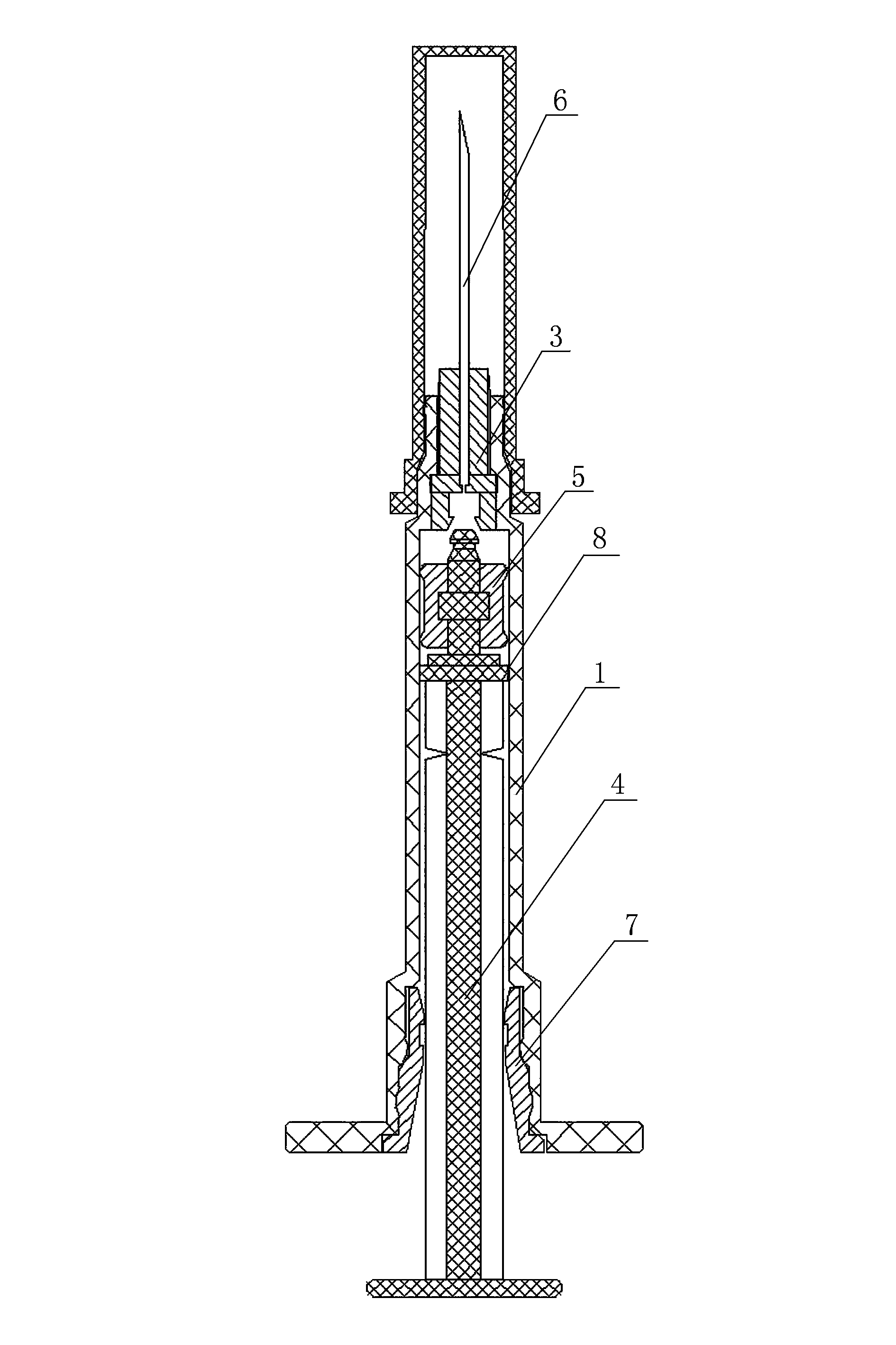
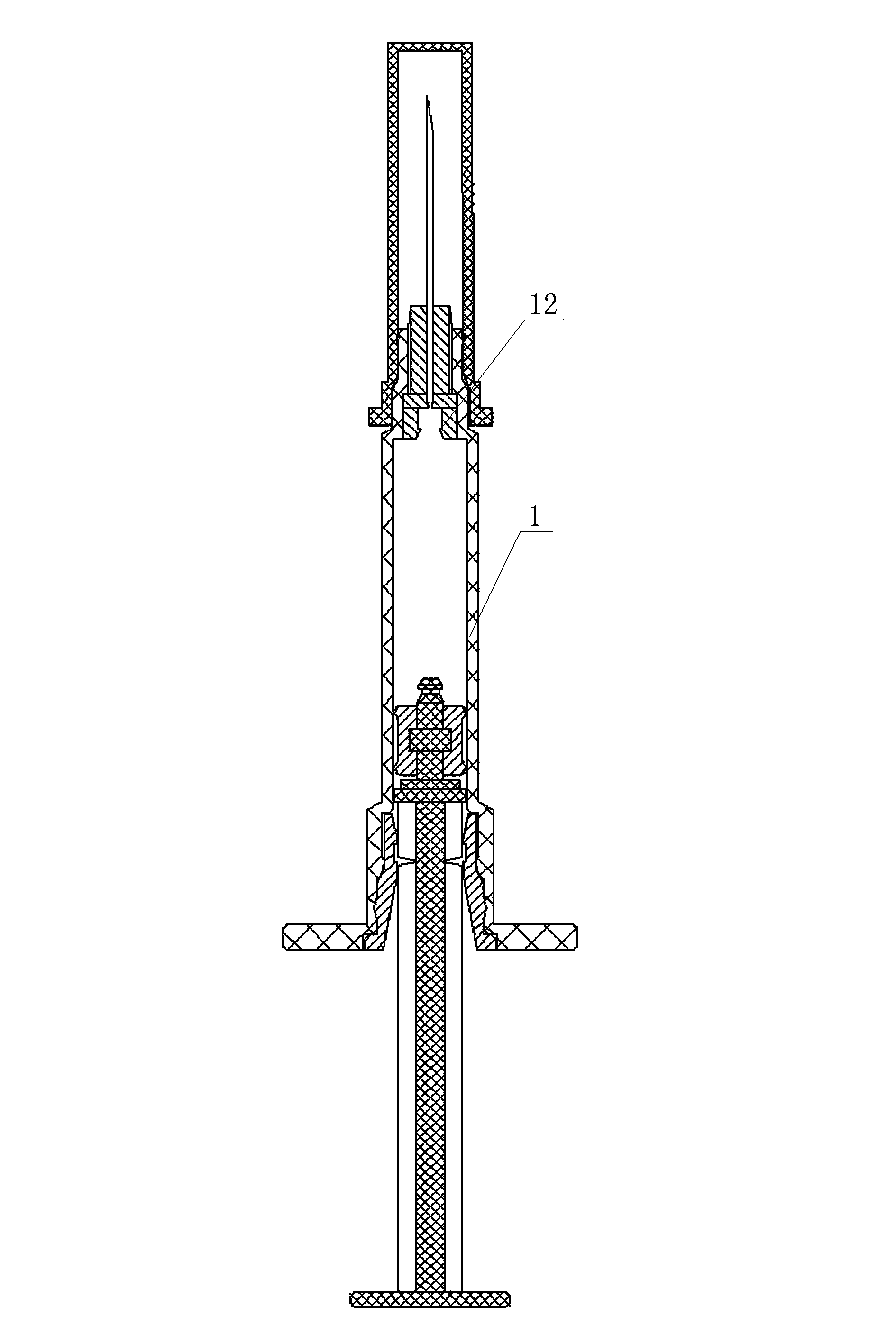
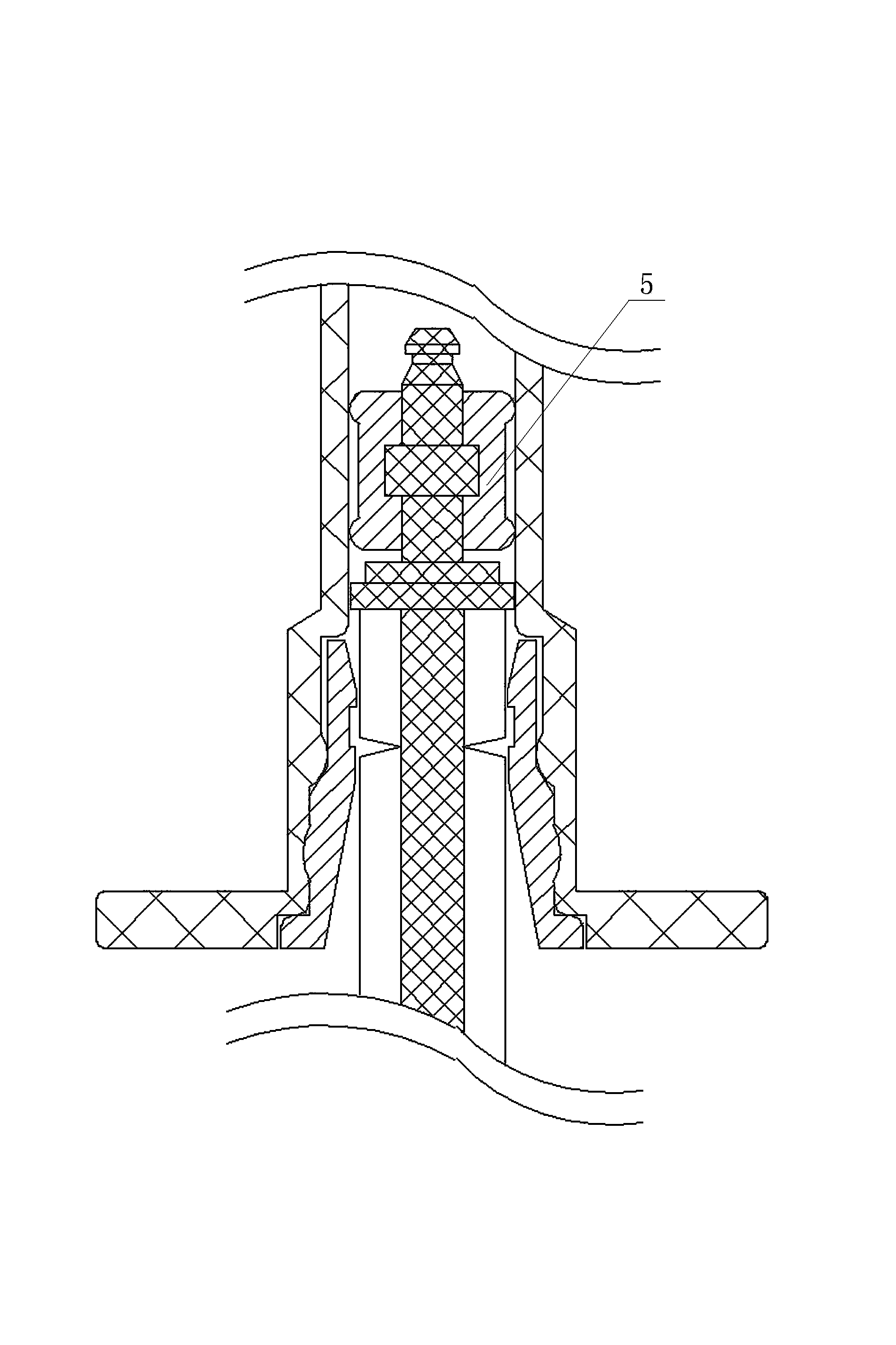
[0029] The present invention is a kind of plunger locking safety syringe, such as figure 1 As shown in , it includes a cylinder body 1, a needle seat 3 is provided in the cylinder neck 2 at the upper end of the cylinder body 1, a core rod 4 is provided inside the cylinder body 1, and a rubber plug 5 is sleeved near the upper end of the core rod 4, The upper end of the needle base 3 is provided with a needle tube 6, which is different from the prior art in that: the inner cavity at the lower end of the needle base 3 is provided with a locking part 9, and the end of the core rod 4 forms a locking pull-back that matches the locking part. Part 10, the inner cavity of the cylinder body 1 near the lower end is provided with a core rod locking piece 7, and the core rod 4 is provided with a self-locking piece 8 that cooperates with the core rod locking piece 7.

[0030] In spec...


PUM


Abstract

The invention discloses a core rod locking-type safety syringe. A needle seat is arranged in a barrel neck on the upper end portion of a barrel, a core rod is arranged in the barrel, a rubber plug is connected at a position, close to the upper end portion, of the core rod in a sleeved manner, and a needle tube is arranged on the upper end portion of the needle seat. The core rod locking-type safety syringe is characterized in that a clamping-matching portion is arranged at a lower-end inner cavity of the needle seat, a locking and pulling-back portion matched with the clamping-matching portion is formed on the end portion of the core rod, a core rod locking member is arranged at a position, close to the inner cavity of the lower end portion, of the barrel, and a self-locking piece matched with the core rod locking member is arranged at the core rod. The core rod locking-type safety syringe has the advantages that the core rod locking member is internally arranged at at a lower-end opening of the syringe barrel, can realize firm meshing with the core rod, can simultaneously realize firm meshing with the inner wall of the barrel and can effectively prevent the core rod from being pushed forwards or pulled backwards in a safe state, so that a needle head portion of the end portion of the core rod is avoided from causing accidental damage to personnel; the core rod locking member is reasonable in product design structure and ingenious in concept, the improved core rod locking member can realize full-automatic assembly of the rear portion, requirements of automatized and large-scale production can be met, and the core rod locking member is easy to popularize and apply in safety syringes and safety self-destroying syringes in various specifications.

Description

technical field [0001] The invention relates to the technical field of medical devices, in particular to a safety syringe with a core rod locking mechanism, and in particular to its mechanical structure. Background technique [0002] Reference document, patent number: ZL201110066497.3, application date: 2011.03.12, patentee: Xu Haohua, this case discloses "a safety syringe with replaceable needle and automatic retraction that can only be used once", including a jacket and Core rod, the core rod is inserted into its inner cavity from the large mouth end of the jacket, and also includes a dispensing needle and an injection needle. The core rod is a cylindrical structure, and the inner cavity of the core rod is provided with a snap ring. A rebound live rod is arranged inside, and the compression spring is looped on the rebound live rod. One end of the compression spring is against the plane of the rebound live rod, and the other end is against the bundle joint plane of the core...

Claims


Application Information

Patent Timeline
Patent Type & Authority Applications(China)
IPC IPC(8): A61M5/178A61M5/315A61M5/50
Inventor 冯兴元
Owner 常州市康福莱医疗用品有限公司
Learn More