Method for straightening stirrer shaft

A technology of agitator and straightening, which is applied in the field of coal chemical industry, can solve the problems of severe shaking and inability to operate the agitator, and achieve the effect of low labor intensity, no installation deviation, and high straightening efficiency

Active Publication Date: 2013-12-18
CHNA ENERGY INVESTMENT CORP LTD +1
View PDF6 Cites 4 Cited by
  • Summary
  • Abstract
  • Description
  • Claims
  • Application Information

AI Technical Summary

Problems solved by technology

When bending to the bottom of the lower shaft 17', the bottom circle runout exceeds the standard, the drive motor 16' outside the tank and the reducer 15' will shake severely, resulting in the failure of the agitator to operate

Method used


Image

  • Method for straightening stirrer shaft
  • Method for straightening stirrer shaft

Examples


Embodiment Construction

[0022] It should be noted that, in the case of no conflict, the embodiments in the present application and the features in the embodiments can be combined with each other. The present invention will be described in detail below with reference to the accompanying drawings and examples.

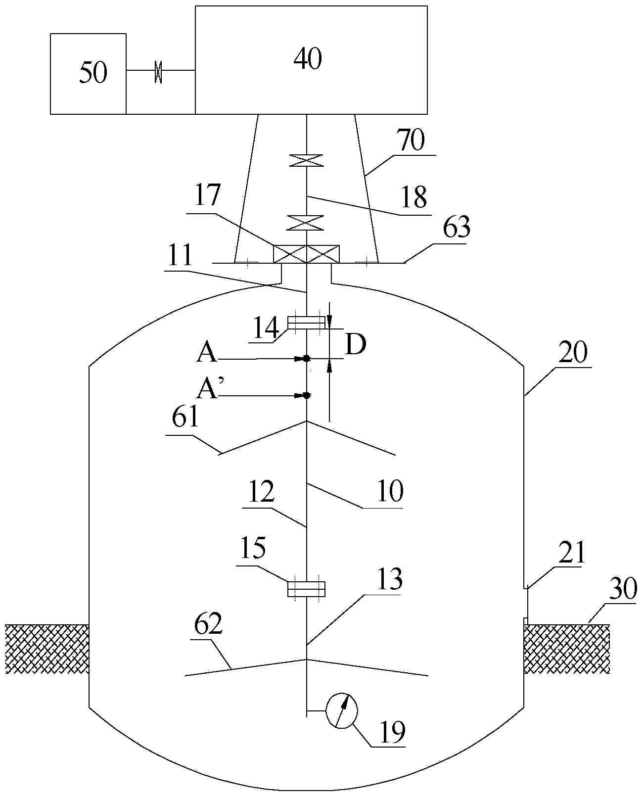
[0023] Such as figure 2 As shown, the present invention provides a method for straightening the shaft of an agitator. Wherein, the agitator shaft 10 is arranged in the tank body 20 , and the straightening method of the agitator shaft includes straightening the agitator shaft 10 in the tank body 20 . This method does not need to move the agitator shaft out of the tank for straightening, and also does not need large-scale machinery and tooling, and does not need special straightening tools. Simple operation, low technical requirements, low labor intensity, no installation deviation, high straightening efficiency and short implementation period. Therefore, the straightening method of the agita...


PUM


Abstract

The invention provides a method for straightening a stirrer shaft. The stirrer shaft is arranged in a tank; the method for straightening the stirrer shaft comprises straightening the stirrer shaft in the tank without moving the stirrer shaft out of the tank, and no large machinery and fixtures are required. The labor intensity is low; no installation deviation is generated; the straightening efficiency is high; by the adoption of the method for straightening the stirrer shaft provided by the invention, the manpower is reduced, and the straightening efficiency is high.

Description

technical field [0001] The invention relates to the field of coal chemical industry, in particular to a method for straightening an agitator shaft. Background technique [0002] The oil-coal slurry of the direct coal liquefaction unit contains a high proportion of solid coal powder (50.9%) and liquid solvent oil (49.1%). Such as figure 1 As shown, in order to prevent the deposition of solid coal dust, a turbine agitator is vertically installed on the tank top of the oil-coal slurry tank body 11 ', and the shaft of the turbine agitator is rigidly connected by three sections of flanges. Bearing 1' is installed on the drive shaft 2' of the oil-coal slurry tank body 11. The bearing 1' is located in the reducer and the joint socket 8'. The bearing 1' is used as the supporting point of the shaft. The lower end of the shaft in the tank is suspended, for example , the intermediate shaft 5' has no support point. [0003] The three-section shaft of the agitator is two sections insi...

Claims


Application Information

Patent Timeline
Patent Type & Authority Applications(China)
IPC IPC(8): B21D3/00B01J8/10
Inventor 刘庆华谢舜敏胡庆斌孔光跃
Owner CHNA ENERGY INVESTMENT CORP LTD
Why Eureka
Try Eureka