Foldable changeable forming device for selective laser melting

A laser selective melting and selective laser melting technology, applied in the field of 3D printing laser selective melting rapid prototyping, can solve the problems of labor consumption, poor effect, time-consuming powder recovery, etc., to improve the labor environment, save the cleaning operation process, Easy-to-use effects

Inactive Publication Date: 2013-12-18
XI AN JIAOTONG UNIV +1
View PDF6 Cites 21 Cited by
  • Summary
  • Abstract
  • Description
  • Claims
  • Application Information

AI Technical Summary

Problems solved by technology

[0006] In order to solve the problems of time-consuming, labor-intensive and poor effect of powder recovery in existing SLM equipment, the purpose

Method used


Image

  • Foldable changeable forming device for selective laser melting
  • Foldable changeable forming device for selective laser melting
  • Foldable changeable forming device for selective laser melting

Examples


Embodiment Construction

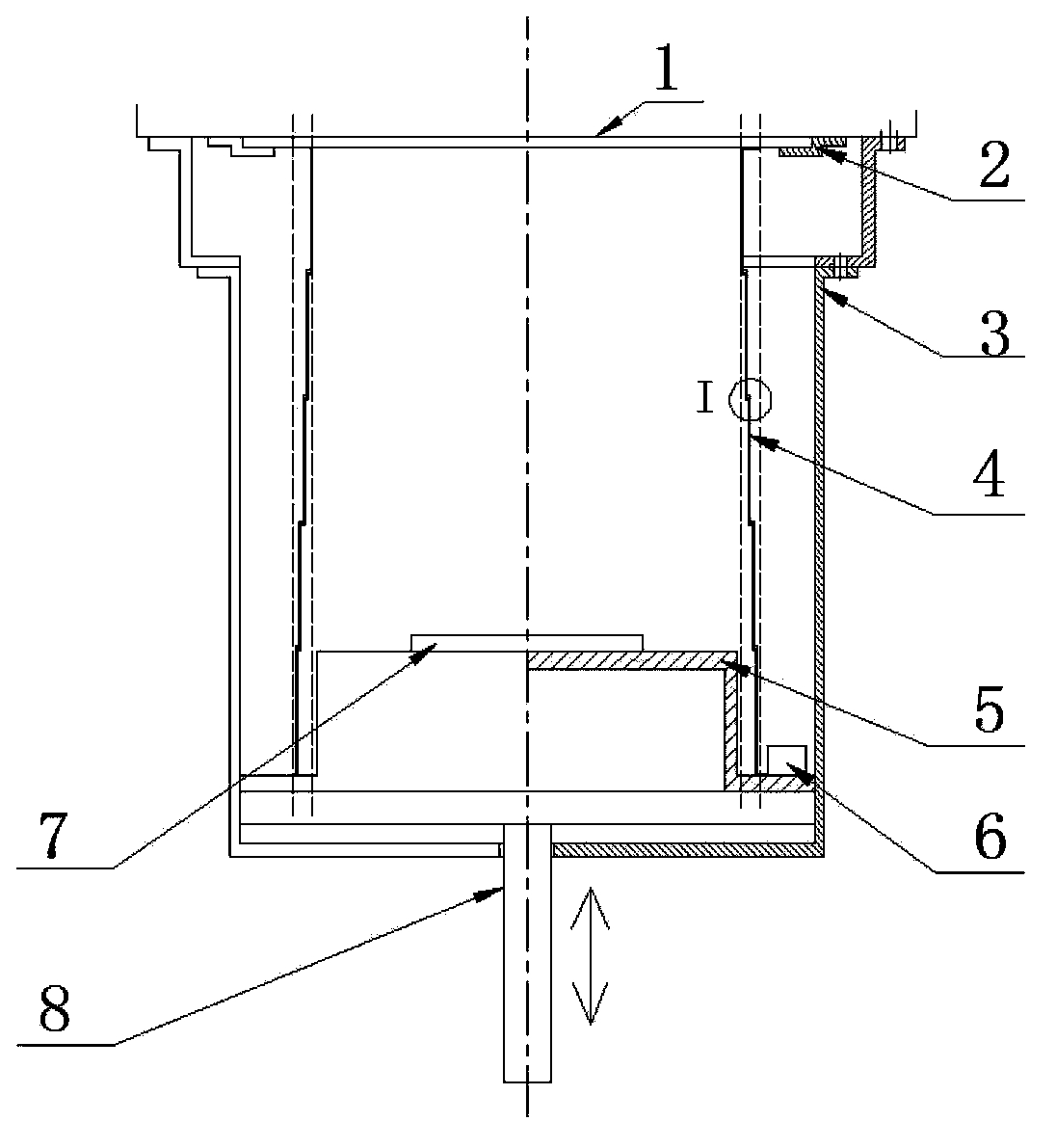
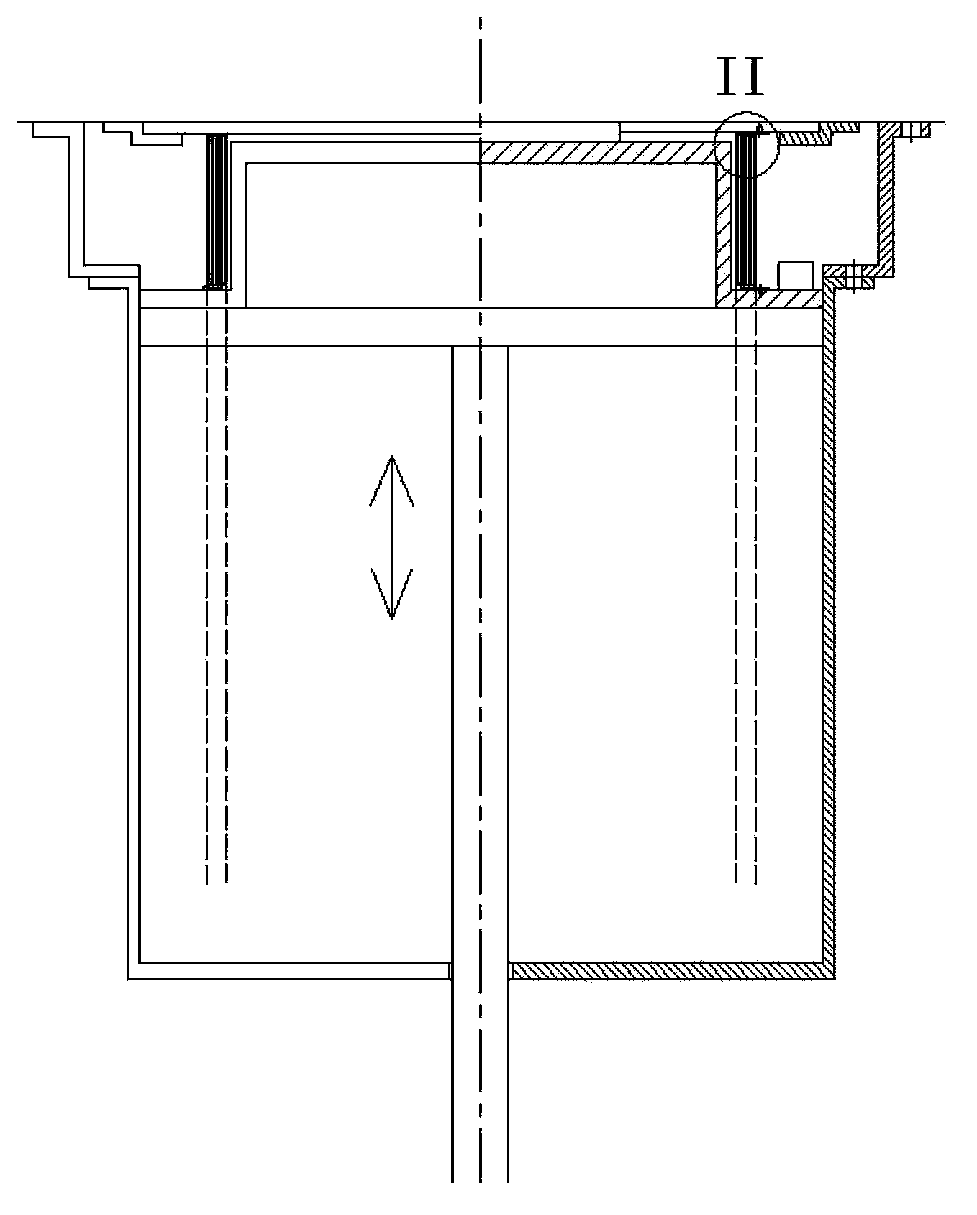
[0021] Such as figure 2 As shown, a foldable and easy-to-change forming device for laser selective melting and forming is set in the cylinder body 3 of the original forming cylinder, including a forming base plate 7, a bottom plate 5, and a telescopic cover 4 that gradually shrinks from bottom to top. The forming substrate 7 is fixed on the base plate 5 , the lower end of the telescoping cover 4 is fixed on the periphery of the base plate 5 , and the base plate 5 is connected to the upper plate of the electric push rod 8 through the clamping member 6 . The upper end of the telescopic cover 4 is connected with the lower surface of the forming surface 1 (connected with the upper end of the original forming cylinder) through the clamping part 2 .

[0022] At the beginning of forming, the electric push rod 8 pushes the bottom plate 5 and the forming base plate 7 up, so that the forming base plate and the forming surface 1 are flush. At this time, the telescopic cover 4 also short...


PUM


Abstract

The invention discloses a foldable changeable forming device for selective laser melting. The foldable changeable forming device is characterized by comprising a forming substrate, a base plate and a telescopic cover reduced from bottom to top gradually. The forming substrate is fixed on the base plate, the lower end of the telescopic cover is fixed to the periphery of the base plate, the base plate is connected with an upper plate of an electric push bar through a lower clamping part, and the upper end of the telescopic cover is connected with the lower surface of a forming face through an upper clamping part. After finishing the forming process, parts can be taken out and residual powder can be cleaned by only removing the foldable changeable forming device.

Description

technical field [0001] The invention relates to a 3D printing laser selective melting rapid prototyping technology, in particular to a metal and nonmetal laser selective melting forming device. Background technique [0002] Selective Laser Melting (SLM) technology is a rapid prototyping technology that can directly form metal parts, and it is one of the main forms of rapid prototyping in 3D printing. The principle of this technique see figure 1 shown. The industrial computer controls the vibrating mirror to scan the selected area according to the sliced ​​CAD model information. The scanned metal powder is melted and bonded together. After one layer is scanned, the feeding cylinder is raised by one layer (the forming cylinder is correspondingly lowered by one layer), and the scraper (or rollers) lay down a layer of powder on the forming surface, and then scan and melt the next layer, forming the final part layer by layer. Since each layer of unmelted powder supports the in...

Claims


Application Information

Patent Timeline
IPC IPC(8): B22F3/105
Inventor 张安峰李涤尘侍行坤杨洪涛张海洋
Owner XI AN JIAOTONG UNIV
Why Eureka
Try Eureka