Synchronous pulley deburring device convenient to control cutting quantity
A technology of synchronous pulley and cutting amount, which is applied in the direction of machine tools, manufacturing tools, grinding/polishing equipment, etc. suitable for grinding the edge of workpieces, and can solve the problems of low turning efficiency, unfavorable product beauty, lathe turning, and product quality randomness Advanced problems, high cutting efficiency, convenient clamping and loosening operation, good clamping effect
- Summary
- Abstract
- Description
- Claims
- Application Information
AI Technical Summary
Problems solved by technology
Method used
Image

Examples
Embodiment 1
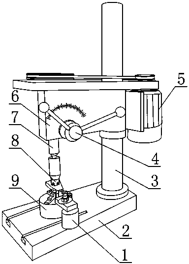
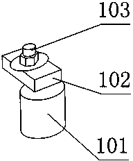
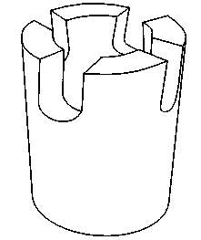
[0029] Such as figure 1 , figure 2 , image 3 and Figure 4 As shown, the synchronous pulley deburring device with easy control of cutting amount includes workbench 2, column 3, lifting device, lifting handle 4, motor 5, frame 6, transmission shaft 7, deburring knife 8, and is used for synchronous pulley A fixed clamping device 9 and a pressing device 1 for fixing the clamping device 9, one end of the column 3 is fixedly connected to the workbench 2, the frame 6 is fixedly connected to the column 3, the motor 5 and the drive shaft 7 are both It is arranged on the frame 6, and the rotating shaft of the motor 5 is connected with the transmission shaft 7, and the lifting device is connected with the lifting handle 4, and the lifting device is connected with the transmission shaft 7, and the lifting handle 4 is located outside the frame 6, and the frame 6 A scale is also provided on the surface close to the lifting handle 4 , the burr knife 8 is fixedly connected to the transm...
Embodiment 2
[0032] This embodiment is further improved on the basis of embodiment 1: as figure 1 , figure 2 , image 3 and Figure 4 As shown, the lifting device includes a gear 41, a transmission shaft sleeve 42, a first bearing 43 and a second bearing 44, the gear 41 is connected with the lifting handle 4, the transmission shaft sleeve 42 is provided with a through hole in the center, and the outer wall is provided with The rack has a cylindrical structure, and the rack on the outer wall of the transmission shaft sleeve 42 meshes with the teeth of the gear 41. The transmission shaft 7 is arranged in the through hole, and the transmission shaft 7 and the transmission shaft sleeve 42 pass through the first The bearing 43 and the second bearing 44 are fixedly connected, and among the first bearing 43 and the second bearing 44, one is a thrust ball bearing and the other is a deep groove ball bearing.
[0033] The set gear 41 is connected with the lifting handle 4, that is, the lifting h...
PUM
 Abstract
Description
Claims
Application Information