
Pipeline system for grinding coolant central filtering and chip removing system

A pipeline system and cooling fluid technology, applied in the direction of grinding/polishing equipment, grinding/polishing safety devices, metal processing equipment, etc., can solve the problems of short service life, increase production cost, unfavorable resource saving, etc., and achieve extension The effect of service life, cost saving and energy saving cost

Inactive Publication Date: 2013-12-18
WUXI D WO SEIKO EQUIP
View PDF0 Cites 2 Cited by
  • Summary
  • Abstract
  • Description
  • Claims
  • Application Information

AI Technical Summary

Problems solved by technology

[0002] At present, the grinding and superfinishing of bearing parts in most bearing manufacturers generally use a stand-alone independent water tank to provide emulsion and superfine liquid as the cooling liquid for the workpiece during processing. Although there is a magnetic separator to separate the grinding iron powder, the cooling liquid The cleanliness is far from meeting the requirements of the bearing production process, which seriously affects the roughness of the bearing surface
[0003] The coolant is repeatedly used in the independent water tank for a long time, and it cannot be fully recycled, so that the coolant is easy to deteriorate, the service life is short, and the production cost is increased. The coolant needs to be better and further processed on a regular basis, which is not only detrimental to resources The saving also affects the environment of the workshop to a certain extent
In addition, the replacement and treatment of the coolant also requires manual operations, which requires a large labor cost, which is not conducive to saving costs. It is urgent to invent a pipeline system that can allow the coolant to be recycled and ensure the accuracy of the coolant.

Method used


Image

  • Pipeline system for grinding coolant central filtering and chip removing system

Examples


Embodiment Construction

[0015] The following will clearly and completely describe the technical solutions in the embodiments of the present invention. Obviously, the described embodiments are only some of the embodiments of the present invention, rather than all the embodiments. Based on the embodiments of the present invention, all other embodiments obtained by persons of ordinary skill in the art without making creative efforts belong to the protection scope of the present invention.

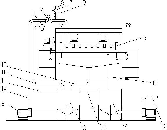
[0016] see figure 1 , the embodiment of the present invention includes:

[0017] A piping system for a centralized filtering chip removal system for grinding coolant, comprising: a dirty liquid main pipe 1 and a clean liquid supply pipe 2, the dirty liquid main pipe 1 is connected to the entrance of a dirty liquid tank 3, and the clean liquid supply pipe 2 is connected to the The outlet of a net liquid tank 4 is connected.

[0018] The outlet of the dirty liquid tank 3 is connected with the inlet of a filter press ...


PUM


Abstract

The invention discloses a pipeline system for a grinding coolant central filtering and chip removing system. The pipeline system comprises a sewage main pipe and a clean liquid supply pipe, wherein the sewage main pipe is connected with the inlet of a sewage box, the clean liquid supply pipe is connected with the outlet of a clean liquid box, the outlet of the sewage box is connected with the inlet of a filter pressing device through a filter pipe, the inlet of the clean liquid box is connected with the outlet of the filter pressing device through a clean liquid pipe, the filter pipe is connected with a filter pump and a butterfly valve, a gas pipe is connected between the butterfly valve and the inlet of the filter pressing device, and the clean liquid pipe is directly communicated with the clean liquid box. Through the arrangement, the pipeline system for the grinding coolant central filtering and chip removing system has the advantages that the sewage is purified and then outputted, the circulation and repeated use are realized, the period of use of the coolant is prolonged, a beautifying effect is played to the fieldwork environment, and energy and cost are saved.

Description

technical field [0001] The invention relates to the field of cooling liquid filtration systems, in particular to a pipeline system for a centralized filtering chip removal system for grinding cooling liquid. Background technique [0002] At present, the grinding and superfinishing of bearing parts in most bearing manufacturers generally use a stand-alone independent water tank to provide emulsion and superfine liquid as the cooling liquid for the workpiece during processing. Although there is a magnetic separator to separate the grinding iron powder, the cooling liquid The cleanliness is far from meeting the requirements of the bearing production process, which seriously affects the roughness of the bearing surface. [0003] The coolant is repeatedly used in the independent water tank for a long time, and it cannot be fully recycled, so that the coolant is easy to deteriorate, the service life is short, and the production cost is increased. The coolant needs to be better and...

Claims


Application Information

Patent Timeline
Patent Type & Authority Applications(China)
IPC IPC(8): B24B55/03
Inventor 邱雪寒潘道清邱林
Owner WUXI D WO SEIKO EQUIP
Learn More