A kind of silicon block cutting method

A cutting method and silicon block technology, which can be used in fine working devices, stone processing equipment, manufacturing tools, etc., can solve the problems of cutting speed, workbench moving speed, low mortar flow rate, poor cutting ability of silicon wafers, saw marks on the surface of silicon wafers, etc. problem, achieve the effect of reducing cutting cost, reducing scrap rate and smooth surface

Inactive Publication Date: 2015-08-19
HENGSHUI YINGLI NEW ENERGY
View PDF7 Cites 0 Cited by
  • Summary
  • Abstract
  • Description
  • Claims
  • Application Information

AI Technical Summary

Problems solved by technology

Since the surface of the steel wire is relatively smooth, the ability to carry mortar is relatively weak, and the ability of the steel wire to cut silicon wafers is poor. In order to meet the cutting effect, more mortar is needed to participate in the cutting, which leads to longer cutting time. It will increase the cost of cutting; in addition, the cutting speed of conventional steel wire, the moving speed of the worktable and the flow rate of mortar are relatively low, the work efficiency is low, and the cost is high
[0007] Diamond steel wire cuts silicon wafers, the cutting speed is relatively fast, and there are shortcomings. Since there is no matching cutting process at present, saw marks will appear on the surface of silicon wafers during the process of cutting silicon wafers, and the silicon powder after cutting is easy to remain in the cutting equipment. On the other hand, it is not easy to clean, and because of the fast cutting speed in cutting with diamond wire, the steel wire is easy to break, and the cost is high

Method used


Image

  • A kind of silicon block cutting method
  • A kind of silicon block cutting method
  • A kind of silicon block cutting method

Examples


preparation example Construction

[0079] The preparation method of the structural wire for silicon block cutting includes the following steps: 1) performing mechanical derusting treatment on the surface of the wire rod; 2) performing chemical surface rust treatment on the wire rod after the mechanical derusting treatment, and then washing and drying; 3) Heating and wire drawing to make semi-finished steel wire; 4) Heat treatment to relieve stress; 5) Heating, passing through the shaping hole mold and wire drawing machine for rotating wire drawing to make steel wire for cutting; 6) Electroplating the outer surface of steel wire for cutting Antioxidant layer, washed with water.

[0080] The material of the wire rod in step 1) is high carbon steel, the carbon content is 0.75%-0.9%, the content of sulfur and phosphorus is less than 0.02%; the anti-oxidation layer in step 6) is a brass alloy layer; the shaping hole mold in step 5) It is a ring whose inner diameter is equal to the diameter of the steel wire, and the...

Embodiment 1

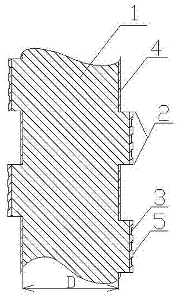
[0085] The outer surface of the steel wire is coated with an anti-oxidation layer 4 , and the outer surface of the steel wire 1 is provided with spiral protrusions 2 . The diameter D of the steel wire 1 is 0.10 mm, and the spiral protrusion 2 is a rectangular thread. On the shaft section, the width of the rectangular thread is 0.10 mm, the distance between the roots of the thread grooves is 0.08 mm, and the thread depth is 0.06 mm. The steel wire 1 is made of high carbon steel, with a carbon content of 0.75%-0.9%, and a sulfur and phosphorus content of less than 0.02%. An anti-oxidation layer 4 is electroplated to attach a relatively dense structure to the surface of the steel wire, which protects the steel wire, prevents the steel wire from being oxidized, and effectively prevents the main body of the steel wire from directly contacting the silicon chip. The anti-oxidation layer 4 is preferably a brass alloy layer to prevent the steel wire from being worn. The design of the ...

Embodiment 2

[0096] A steel wire for cutting silicon wafers, comprising a steel wire 1, the outer surface of the steel wire 1 is coated with an anti-oxidation layer 4, and the outer surface of the steel wire 1 is provided with spiral protrusions 2. The diameter D of the steel wire 1 is 0.15 mm, and the spiral protrusion 2 is a rectangular thread. On the shaft section, the width of the rectangular thread is 0.20 mm, the distance between the roots of the thread grooves is 0.07 mm, and the thread depth is 0.08 mm.

[0097] The spiral protrusion 2 is provided with a small groove 3, and the small groove 3 is wound along the direction of the spiral protrusion 2. There are three small grooves 3 with a rectangular cross-section; the width of the small grooves 3 is 0.02 mm, the depth is 0.017 mm, and the width of the small protrusions 5 between adjacent small grooves 3 is 0.035 mm. The design of the small groove 3 is convenient for the steel wire to hold some ground silicon powder in the process of...


PUM

PropertyMeasurementUnit
diameteraaaaaaaaaa
widthaaaaaaaaaa
diameteraaaaaaaaaa

Abstract

The invention discloses a silicon-block cutting method, which relates to the technical field of crystalline-silicon manufacture. The method comprises the following steps of respectively preparing the usage amounts of recycled silicon carbide and a recycled suspending liquid used in mortar as 40 to 100 percent, modulating the density of the mortar as 1.625 to 1.635kg / L, and adding the mortar according to the effective cutting length of a silicon block in the cutting process, wherein the adding proportion of the added mortar is 0.235 to 0.3L / mm, and the adding amount of the mortar is equal to the effective cutting length of the silicon block multiplied by the adding proportion of the mortar; selecting a guiding wheel to enable the notch of the guiding wheel to be matched with a steel wire; setting the cutting speed of the steel wire as 12 to 14m / s, the moving speed of a worktable as 250 to 330mu m / min and the flow quantity of the mortar as 130 to 160kg / min, cutting the silicon block, and cooling; cutting a structural wire, the outer surface of which is provided with spiral bulges and is coated with an anti-oxidation layer by the steel wire. According to the invention, through the technical matching property of the cutting speed of the steel wire, the moving speed of the worktable and the flow quantity of the mortar, the updating of the mortar is reduced, the production cost can be lowered, the rate of fragments generated in silicon-block cutting is reduced, the rate of finished products is increased, and the quality of the products is improved.

Description

technical field [0001] The invention relates to the technical field of crystalline silicon production. Background technique [0002] At present, in the solar energy industry, the processing of silicon wafers refers to cutting silicon blocks into silicon wafers of a certain thickness. The cutting of silicon block is mainly driven by steel wire and mortar cutting. Mortar consists of suspension and silicon carbide. In the processing of silicon wafers, steel wires, mortar, and guide wheels are required to participate. At the same time, the high-speed rotation of the steel wires and the continuous flow of mortar on the steel wires are required to complete the cutting of silicon wafers. Specific cutting process: the steel wire with a certain tension rotates horizontally at high speed under the drive of the guide wheel, the mortar flows on the steel wire continuously, and the viscous suspension can carry silicon carbide and attach to the rotating steel wire. As the block of sili...

Claims


Application Information

Patent Timeline
Patent Type & Authority Patents(China)
IPC IPC(8): B28D5/04
Inventor 任军海
Owner HENGSHUI YINGLI NEW ENERGY
Why Eureka
Try Eureka