
3D printer heating plate supporting transmission structure

A technology of 3D printers and transmission structures, applied in printing devices, printing, etc., can solve the problems of inconvenient disassembly, large screw friction coefficient, low transmission efficiency, etc., and achieve the effect of simplifying the post-processing process

Active Publication Date: 2013-12-18
GUILIN UNIV OF ELECTRONIC TECH
View PDF12 Cites 0 Cited by
  • Summary
  • Abstract
  • Description
  • Claims
  • Application Information

AI Technical Summary

Problems solved by technology

This places high requirements on the positioning of the four fixing points that fix the two slide rails, and it is difficult to ensure the accuracy of the system, which increases the difficulty of installation.
[0004] Another disadvantage of the above structure is that once the two cylindrical slide rails are installed, it is inconvenient to disassemble, which is not conducive to the maintenance and upgrading of the machine in the later period
[0005] Another disadvantage is that the cylindrical slide rail is used as the support structure of the heating plate, and when the heating plate slides, it will inevitably produce a large noise
[0006] The transmission structure of the screw has some of the disadvantages mentioned above, and also has its own inconveniences: for example, the transmission efficiency is low, the friction coefficient of the screw itself is large, and the rotation rate is limited, which reduces the work of the entire mechanical system. efficiency

Method used


Image

  • 3D printer heating plate supporting transmission structure
  • 3D printer heating plate supporting transmission structure
  • 3D printer heating plate supporting transmission structure

Examples


Embodiment Construction

[0019] The technical scheme of the present invention will be further described below in conjunction with the drawings.

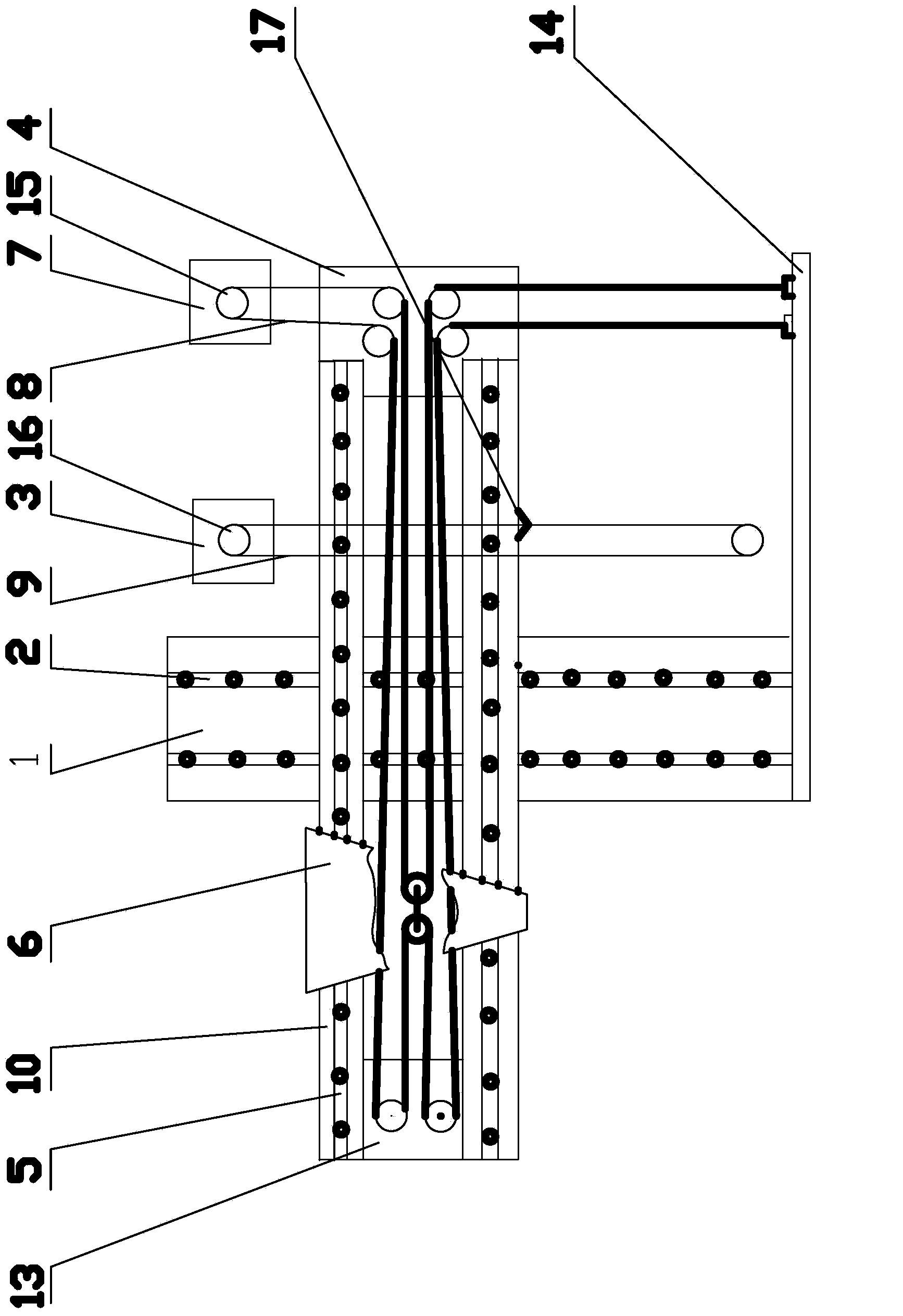
[0020] The heating plate support transmission structure of the 3D printer of the present invention is composed of an upper X-direction support transmission device and a lower Y-direction support transmission device.

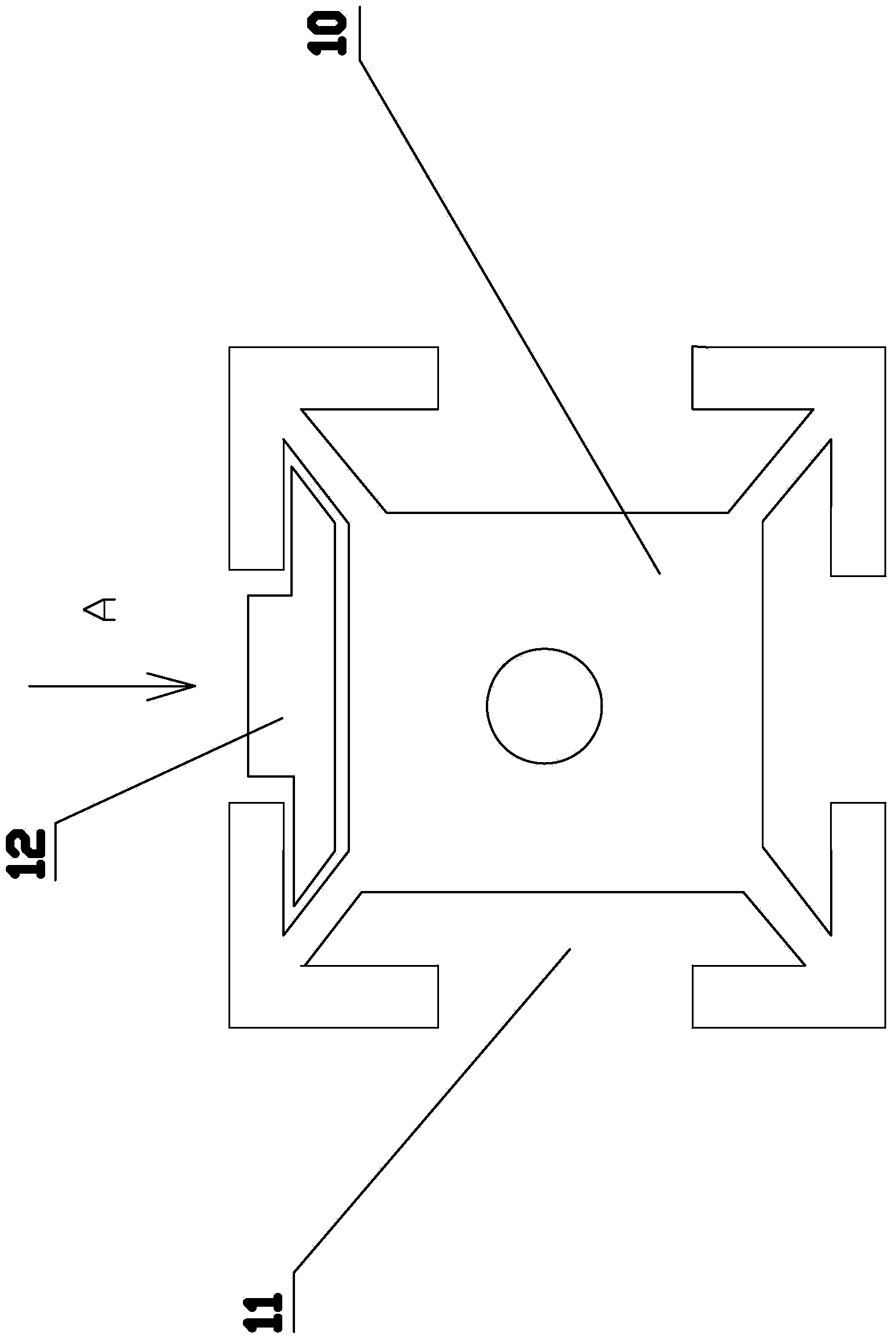
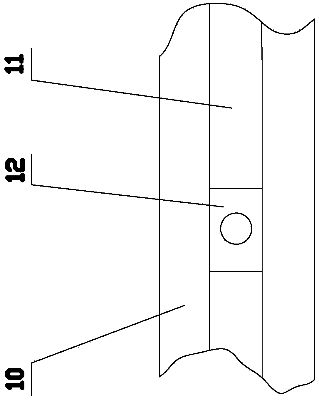
[0021] The Y-direction supporting transmission device is mainly composed of a base frame 1, a Y-direction linear guide rail 2, a Y-direction sliding block, a Y-direction stepping motor 3, and a Y-direction pulley transmission mechanism. Wherein, the length direction of the base frame 1 is the Y-axis direction, two Y-direction linear guide rails 2 are laid on the base frame 1, and the Y-direction sliding block is slidably fitted on the two Y-direction linear guide rails 2. The stepping motor 3 is arranged at the rear end beside the base frame 1. The Y-direction pulley transmission mechanism includes a Y-direction belt 9 and two pulleys. A Y-direction...


PUM


Abstract

The invention discloses a 3D printer heating plate supporting transmission structure which comprises an X-direction supporting transmission device and a Y-direction supporting transmission device. The Y-direction supporting transmission device comprises a chassis, two Y-direction linear guide rails arranged on the chassis, Y-direction sliding blocks matched with the Y-direction linear rails and a Y-direction belt pulley transmission mechanism driven by a Y-direction stepping motor. The X-direction supporting transmission device comprises a supporting frame, two X-direction linear guide rails arranged on the supporting frame, X-direction sliding blocks matched with the X-direction linear guide rails, a heating plate supporting a printer heating platform and an X-direction belt pulley transmission mechanism driven by an X-direction stepping motor. The heating plate is arranged on the X-direction sliding blocks, and the supporting frame is arranged on the Y-direction sliding blocks. According to the 3D printer heating plate supporting transmission structure, the movement of the heating plate in the X-axis direction and the movement of the heating plate in the Y-axis direction are completely independent and do not affect each other, displacement compensation between the X-axis direction displacement and the Y-axis direction displacement of the heating plate do not need to be computed, and post processing processes of data are simplified.

Description

(1) Technical field: [0001] The invention relates to the internal structure of a printer, in particular to a 3D printer heating plate supporting transmission structure. (2) Background technology: [0002] At present, the structure used to support and drive the heating plate of a 3D printer generally adopts a cylindrical slide rail support and screw drive system. [0003] As a support structure, cylindrical slides have many disadvantages. For example, cylindrical sliding rails generally adopt a fixing method with two ends fixed, and two parallel rails are often used as a whole, and the two cylindrical sliding rails must be completely parallel to ensure accuracy. This places high requirements on the positioning of the four fixed points for fixing the two slide rails, which makes it difficult to ensure the accuracy of the system and increases the difficulty of installation. [0004] Another disadvantage of the above structure is that once the two cylindrical slide rails are installed,...

Claims


Application Information

Patent Timeline
Patent Type & Authority Applications(China)
IPC IPC(8): B41J29/00
Inventor 何晓建颜学龙潘鑫龙于海波
Owner GUILIN UNIV OF ELECTRONIC TECH
Learn More