Rope wheel with self-locking device

A technology of self-locking device and rope wheel, which is applied in hoisting device and clockwork mechanism, etc., can solve the problems of high labor intensity, broken rope, falling of heavy objects, etc., and achieve the effect of reducing safety risks and improving work efficiency

Inactive Publication Date: 2013-12-18
STATE GRID CORP OF CHINA +1
View PDF11 Cites 14 Cited by
  • Summary
  • Abstract
  • Description
  • Claims
  • Application Information

AI Technical Summary

Problems solved by technology

In the process of using the rope wheel, occasionally the rope will be broken, resulting in a safety accident that the heavy object will fall, directly threatening the safety of the operator and the power transmission equipment
Moreover, when using rope wheels to transport tools and materials up and do

Method used


Image

  • Rope wheel with self-locking device
  • Rope wheel with self-locking device
  • Rope wheel with self-locking device

Examples


Embodiment 1

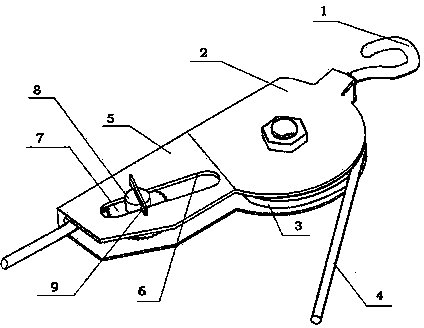
[0017] figure 1 The sheave with self-locking device shown in the embodiment includes a runner 3, a steel wire rope 4, a support frame 2, and a self-locking device is also included on the support frame 2, and the steel wire rope 4 passes through the self-locking device.

[0018] Further explain the present embodiment, since the sheave is fixed, a self-locking device is installed on the sheave, the self-locking device and the support frame 2 of the sheave are directly fixed, and the wire rope 4 of the sheave is passed through the self-locking device out. The beneficial effect produced in this way is that after the rope wheel and the self-locking device are fixed together, it is convenient to carry the whole tool body, and the rope wheel also passes through the self-locking device during the process of threading the steel wire rope 4, so there is no need to repeatedly thread the wire during installation . The purpose of installing a self-locking device on the sheave is to prev...

Embodiment 2

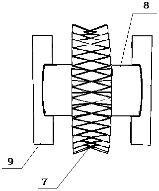
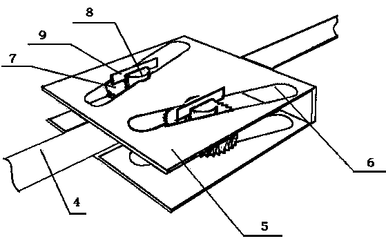
[0025] Such as image 3 The difference between the self-locking device shown in this embodiment and the first embodiment is that the self-locking device includes two rollers 7 and two pairs of slotted holes 6 .

[0026] Further explain the present embodiment: the structure of the self-locking device in the present embodiment is different from the self-locking device of embodiment 1. Two rollers 7 are used to rub and squeeze the steel rope 4. When the steel rope 4 descends, the two rollers 7 descend simultaneously. Squeeze and lock the wire rope 4 from two directions at the same time, so that the wire rope 4 can be locked after falling a small distance. The beneficial effect of this embodiment is that the wire rope can be locked more accurately and quickly, improving work efficiency and ensuring the safety of operators.


PUM


Abstract

The invention discloses a rope wheel with a self-locking device and relates to the technical field of brake or stop devices. The rope wheel with the self-locking device comprises a turning wheel, a steel rope and a supporting frame, wherein the self-locking device is also arranged on the supporting frame; the steel rope passes through the self-locking device; the self-locking device comprises a U-shaped fixing plate and a roller; a pair of long slotted holes is formed in the same positions of two side plates of the U-shaped fixing plate; wheel teeth are arranged on the roller; a wheel shaft is fixed on the axis of the roller; the two ends of the wheel shaft are in sliding fit with the pair of long slotted holes; the included angle between the length direction of the long slotted holes and the U-shaped groove bottom of the U-shaped fixing plate is an acute angle; the smallest gap between the wheel teeth of the roller and the U-shaped groove bottom is smaller than the diameter of the steel rope. The rope wheel with the self-locking device has the beneficial effects that when the roper wheel is used for vertically conveying tools and materials, the steel rope dropping downwards is locked, and the weight falling accident is prevented; in addition, the steel rope can be locked at any height, and the tools and the materials can be conveniently taken down by operators.

Description

technical field [0001] The invention relates to the application technical field of braking or stopping devices. Background technique [0002] At present, along with the increasing number of power transmission elevated iron towers, some rope pulleys are needed when the upper part of the iron tower is being overhauled, tools and materials are conveyed up and down. In the process of using the rope pulley, occasionally the rope will be broken, causing a safety accident that the heavy object will fall, directly threatening the safety of the operator and the power transmission equipment. Moreover, when using the rope wheel to transport the tools and materials up and down, the operator needs to keep the tools and materials at a certain height as required, and the labor intensity of the operator is high and there is a certain safety risk. [0003] Also do not have at present a kind of rope pulley braking device that can effectively prevent heavy objects from falling after the rope ...

Claims


Application Information

Patent Timeline
IPC IPC(8): B66D1/54B66D1/28B66D5/16
Inventor 何成立杨另轩曹海林申金龙崔延平
Owner STATE GRID CORP OF CHINA
Why Eureka
Try Eureka