
Shielding box for vacuum coating

A technology of vacuum coating and shielding box, which is applied in vacuum evaporation coating, sputtering coating, ion implantation coating, etc. It can solve the problems of unstable metal layer adhesion, difficult cleaning, coating defects of the coated workpiece, etc., to achieve Improve optical and mechanical properties, reduce the loss of manpower and material resources, and reduce the effect of coating defects

Active Publication Date: 2013-12-18
JIANGSU YITA NEW MATERIAL TECH
View PDF3 Cites 2 Cited by
  • Summary
  • Abstract
  • Description
  • Claims
  • Application Information

AI Technical Summary

Problems solved by technology

[0002] During the vacuum coating process, when the metal vapor emitted by the coating source is deposited on the workpiece to be coated, it will also be partially sputtered on the inner wall of the coating chamber, resulting in the accumulation of metal layers on the inner wall of the chamber over time. On the one hand, it will affect the working effect of the chamber, on the other hand, it is not easy to clean up, causing unnecessary loss of manpower and material resources
Moreover, as the number of times or time of coating increases, the metal layer deposited on the inner wall of the coating chamber becomes thicker and thicker, and these metal layers are not firmly attached to the surface of the cavity wall, and metal residues are very easy to fall on the surface during the coating process. On the workpiece to be plated, causing coating defects on the workpiece to be plated

Method used


Image

  • Shielding box for vacuum coating

Examples


Embodiment Construction

[0014] The present invention will be further described below in conjunction with the accompanying drawings and embodiments.

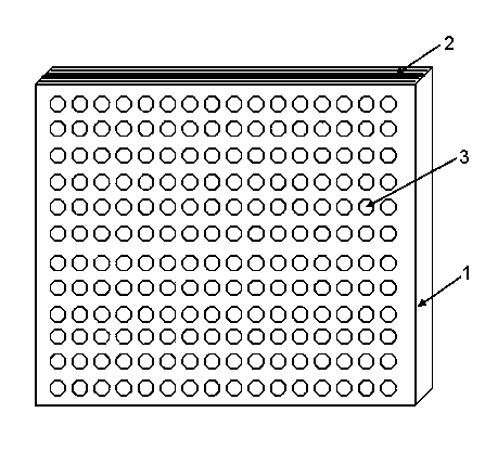
[0015] like figure 1 Shown: a shielding box for vacuum coating, including a casing 1 and a shielding sheet 2, the casing 1 and the shielding sheet 2 are made of steel, copper, aluminum or alloy materials, and inside the casing 1 there are multiple Independently arranged shielding sheets 2, the shielding sheets 2 are arranged in parallel with each other and each shielding sheet 2 is provided with a plurality of through holes 3, the through holes 3 are evenly distributed on the shielding sheets 2 and the through holes on any two shielding sheets 2 The holes 3 are all corresponding to each other. Specifically, the housing 1 is shaped like an “凵” and grooves are formed on the inner wall of the housing 1 , and each shielding piece 2 is inserted into the housing 1 along the corresponding groove.

[0016] The shielding box adopted in the present invention ha...


PUM


Abstract

The invention discloses a shielding box for vacuum coating, which comprises a housing (1) and a plurality of shielding sheets (2). The shielding box is characterized in that the plurality of independently arranged shielding sheets (2) are arranged in the housing (1); the shielding sheets (2) are arranged in parallel; each shielding sheet (2) is provided with a plurality of through holes (3).Since the shielding box is provided with the independent shielding sheets and each shielding sheet is provided with the through holes, the shielding box can effectively adsorb the metal layer in the repeated coating or long-time coating process, and the metal residues can not fall to the coated workpiece, thereby reducing the coating defects of the coated workpiece, and achieving the goal of improving the optical and mechanical properties of the coated film layer. The independent shielding sheets can be easily extracted and separated and independently cleaned, thereby effectively reducing the unnecessary loss of human resources and material resources. The shielding box has the characteristics of simple structure and high adsorption efficiency, and is convenient to use; the shielding box can be independently or combinedly installed in a proper position near the coating source in the coating chamber.

Description

technical field [0001] The invention relates to the field of coating technology, in particular to a shielding box for vacuum coating that enhances the adsorption capacity of a coating chamber to a metal layer and prevents metal residues from falling on a workpiece to be coated during the coating process. Background technique [0002] During the vacuum coating process, when the metal vapor emitted by the coating source is deposited on the workpiece to be coated, it will also be partially sputtered on the inner wall of the coating chamber, resulting in the accumulation of metal layers on the inner wall of the chamber over time. On the one hand, it will affect the working effect of the chamber, on the other hand, it is not easy to clean up, causing unnecessary loss of manpower and material resources. Moreover, as the number of times or time of coating increases, the metal layer deposited on the inner wall of the coating chamber becomes thicker and thicker, and these metal laye...

Claims


Application Information

Patent Timeline
Patent Type & Authority Applications(China)
IPC IPC(8): C23C14/56
Inventor 王朝阳宫睿
Owner JIANGSU YITA NEW MATERIAL TECH
Learn More