Toothless synchronizing ring and synchronizer

A technology of synchronizing ring and tooth shape, applied in clutches, mechanical drive clutches, mechanical equipment, etc., can solve the problems of high cost and complicated manufacturing process, and achieve the effect of reducing manufacturing cost, simple manufacturing and realizing guiding effect.

Active Publication Date: 2013-12-18
WUXI HIGHLAND DRIVELINE TECH
8 Cites 2 Cited by

AI-Extracted Technical Summary

Problems solved by technology

In the existing synchronizer, the structure of the synchronous ring is as follows figure 1 As shown, the base body 100 comprising a circular ring is provided with an inner tapered hole 200, and the end side of the base body 100 located at the large diameter end of the inner tapered hole 200 has a flange part 1001, and the outer circumference of the flange part 1001 is provided with There are spline teeth 300, and the spline teeth 300 and the spline teeth of the gear holder in the synchronizer are oppositely connected to ...

Abstract

The invention discloses a synchronizer. The synchronizer comprises a tooth holder, wherein a joint tooth sleeve is sleeved on the tooth holder and is movably connected with the tooth holder through a spline; toothless synchronizing rings are arranged on both sides of the tooth holder; inner conical surfaces of the toothless synchronizing rings are in floating connection with outer conical surfaces of conical rings; a joint tooth ring is connected with the end face of each conical ring through an end face groove of the joint tooth holder in a spline matching manner; each toothless synchronizing ring comprises an annular basal body; each basal body is provided with an inner conical hole; one end of each basal body at a large-diameter end of the corresponding inner conical hole is provided with a flange end; at least three locking grooves are uniformly distributed on the outer circumferential edge of each basal body along the axial direction; the grooves are stepped; locking bumps are provided with wide tooth-shaped convex parts; after the locking bumps are embedded in the grooves, the wide tooth-shaped convex parts are positioned on the outer circumferential surface of the flange and protrude outwards along the radial direction. A circle of spline teeth on the flange end of the synchronizing ring are substituted by a small amount of locking bumps, and the locking bumps and the basal bodies of the synchronizing rings are made into split structures, so that the toothlessness of the synchronizing structure is realized, and further the structures and the manufacturing of the synchronizing ring and the synchronizer are simplified.

Application Domain

Mechanical actuated clutches

Technology Topic

EngineeringFlange +2

Image

  • Toothless synchronizing ring and synchronizer
  • Toothless synchronizing ring and synchronizer
  • Toothless synchronizing ring and synchronizer

Examples

  • Experimental program(1)

Example Embodiment

[0018] The specific implementation manner of the present invention will be described below in conjunction with the accompanying drawings.
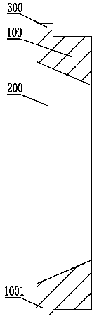
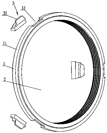
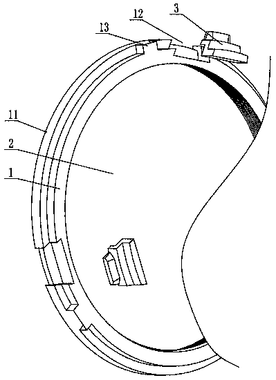
[0019] See figure 2 , the present invention comprises an annular base body 1, the base body 1 is provided with an inner tapered hole 2, and one end of the base body 1 located at the large diameter end of the inner tapered hole 2 is provided with a flange end 11, and the outer peripheral surface of the base body 1 is axially At least three grooves 12 are evenly distributed, the grooves 12 are stepped, and the locking protrusion 3 has a wide tooth-shaped protrusion 31. After the locking protrusion 3 is embedded in the groove 12, the wide tooth-shaped protrusion The portion 31 is located on the outer circumferential surface of the flange end 11 and protrudes radially outward.
[0020] Specifically, the two side arms of the recess on the flange end 11 of the stepped groove 12 have side recesses, the side recesses open toward the groove 12, the locking projection 3 is stepped, and the wide tooth-shaped protrusion 31 is located on the uppermost step of the locking projection 3, and the uppermost step exceeds the wide-tooth-shaped protrusion 31 on both sides of the circumferential direction of the flange end 11, and the part beyond the wide-tooth-shaped protrusion 31 is embedded in the Undercut.
[0021] See image 3 , Figure 4 At least three positioning protrusions 13 or at least three positioning grooves 14 are evenly distributed on the outer peripheral surface of the base 1 between the narrow end of the inner tapered hole 2 and the flange end 11 .
[0022] image 3 , Figure 4 As a preferred embodiment of the present invention, the number of locking projections 3, positioning projections 13, and positioning grooves 14 are three, Figure 5 It is an exploded schematic diagram of the main structure of the synchronizer adopting the synchronization ring of the present invention. See Figure 5 , the synchronizer of the present invention includes a tooth seat 5, the engaging tooth sleeve 4 is sleeved on the tooth seat 5, and is movably connected with the tooth seat 5 through a spline, and both sides of the tooth seat 5 are provided with synchronous rings 6, Cone ring 7 and joint ring gear 8, synchronous ring 6 adopts toothless synchronous ring according to the present invention, the outer peripheral surface between the narrow end of inner tapered hole 2 of synchronous ring 6 and the flange end 11 and the inner surface of tooth seat 5 The circumferential surfaces are connected, and are engaged and connected with corresponding grooves or corresponding protrusions on the inner circumferential surface of the tooth holder 5 through the positioning protrusions 13 or positioning grooves 14, and the inner circumferential surface of the engaging tooth sleeve 4 corresponds to the locking protrusion The position of the block 3 is provided with a groove engaging the wide-tooth-shaped protrusion 31, and the circumference diameter of the outer edge of the locking protrusion 3 is the same as or similar to the diameter of the addendum circle of the spline teeth on the outer circumference of the tooth seat 5, When shifting gears, the engaging tooth sleeve 4 can slide in the gap between the tooth grooves between the outer spline teeth on the tooth seat 5 and the gap between the wide tooth-shaped convex parts 31, and through the toothless synchronous ring and the cone of the present invention The friction of the tapered surface of the ring 7 realizes the rapid synchronization of the engaging tooth sleeve 4 and the engaging ring gear 8, and at the same time, it can prevent the gears from meshing before synchronization and realize the locking effect.
[0023] The above description is an explanation of the present invention, not a limitation of the invention. For the limited scope of the present invention, please refer to the claims. Within the protection scope of the present invention, any form of modification can be made.

PUM

no PUM

Description & Claims & Application Information

We can also present the details of the Description, Claims and Application information to help users get a comprehensive understanding of the technical details of the patent, such as background art, summary of invention, brief description of drawings, description of embodiments, and other original content. On the other hand, users can also determine the specific scope of protection of the technology through the list of claims; as well as understand the changes in the life cycle of the technology with the presentation of the patent timeline. Login to view more.

Similar technology patents

Body condition measuring device

InactiveUS20050234351A1simple structure
Owner:DENSO CORP

Magnetic cooling apparatus and control method thereof

ActiveUS20130180263A1simple structure
Owner:SAMSUNG ELECTRONICS CO LTD

Traditional Chinese medicinal material sieving device facilitating sand removal

InactiveCN109261481ARealize the guiding roleImprove the effect
Owner:新邵南陌生物科技有限公司

Dual-Drivetrain of Power-Assist Vehicle

InactiveUS20100181130A1enhance uphill momentumsimple structure
Owner:CHOU WEN CHENG

Classification and recommendation of technical efficacy words

  • Simple structure
  • Realize the guiding role

Sharing system for air-conditioning coat

InactiveCN107440179ASimple structureeasy to wear
Owner:QINGDAO HAIER AIR CONDITIONER GENERAL CORP LTD

Feeding device of sorter of batteries plate

InactiveCN101357717ASimple structurecooperate well
Owner:NANJING NORMAL UNIVERSITY

Emergency parachuting device and method for multiple-rotor unmanned aerial vehicle

InactiveCN103895870Aavoid aircraft crashSimple structure
Owner:SOUTH CHINA AGRI UNIV +1

Traditional Chinese medicinal material sieving device facilitating sand removal

InactiveCN109261481ARealize the guiding roleImprove the effect
Owner:新邵南陌生物科技有限公司
Why Eureka
Try Eureka