Laser device

A laser and laser technology, applied in the field of lasers, can solve the problems of low power of red light, large deviation of guiding position, easy to be affected by temperature changes, etc., and achieve the effect of reducing cost, ensuring stability, ensuring brightness and guiding.

Inactive Publication Date: 2016-08-03
MAXPHOTONICS CORP
View PDF4 Cites 0 Cited by
  • Summary
  • Abstract
  • Description
  • Claims
  • Application Information

AI Technical Summary

Problems solved by technology

[0004] 1. When the red light is coupled into the optical path of the laser, at least one red light coupling point needs to be added to the beam combiner of the laser, so when the beam combiner is manufactured, an additional coupling arm for red light coupling should be added to make the beam combiner The coupling arm is changed from the original N*1 structure to (N+1)*1, and the coupling efficiency of the pump light and the red light of the laser must be taken into account, which increases the difficulty and cost of the beam combiner
[0005] 2. The power of red light is generally not high, and when the red light passes through the ytterbium-doped fiber of the laser, it will be absorbed by the ytterbium-doped fiber, and the power of the red light will be severely reduced, so the output red light is not bright enough and has poor guidance
[0006] 3. The fiber of the optical path of the red light relative to the laser is a cut-off light wave, and its transmission is a high-order mode. After the red light passes through the beam combiner, most of the energy will be concentrated in the fiber cladding, the transmission loss is large and the light diverges, and the guiding intensity is weak. And the guide position deviation is large
[0007] 4. After the red light is coupled to the optical path of the laser, it is easily affected by high-power lasers. It is necessary to add a red light protector to increase the cost. In addition, the red light semiconductor laser that outputs red light is also easily affected by temperature changes, and the work is unstable.
[0008] 5. Red semiconductor lasers require additional circuit drive, which increases the cost

Method used


Image

  • Laser device
  • Laser device
  • Laser device

Examples


Embodiment Construction

[0025] The present invention will be described in detail below in conjunction with the drawings and embodiments.

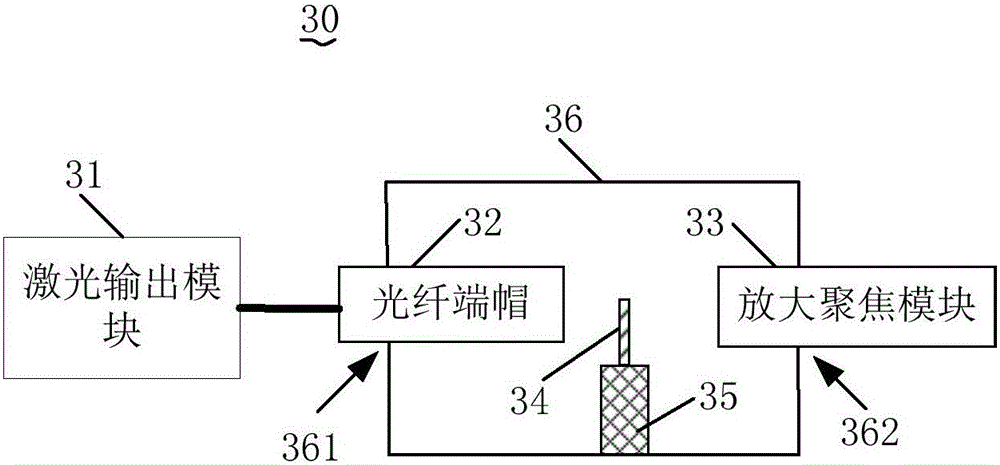
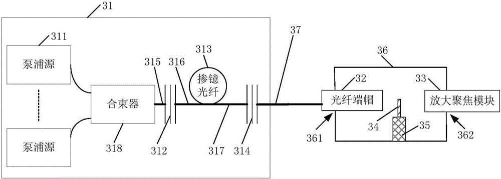
[0026] See figure 2 , The laser 30 includes a laser output module 31, an optical fiber end cap 32, an amplifying and focusing module 33, and a frequency doubling wafer 34.

[0027] The laser output module 31 is used to output laser. The fiber end cap 32 is connected to the laser output module 31 and is used to receive and output the laser light output by the laser output module 31. The magnifying and focusing module 33 is disposed opposite to the fiber end cap 32 so that the laser light output from the fiber end cap 32 is incident on the magnifying and focusing module 33. The frequency doubling wafer 34 is arranged between the fiber end cap 32 and the magnifying and focusing module 33, and is located in the transmission direction of the laser light output from the fiber end cap 32, so that at least part of the laser light output from the fiber end cap 32 is from the ...


PUM


Abstract

The invention discloses a laser, comprising: a laser output module for outputting laser light; an optical fiber end cap connected to the laser output module for receiving and outputting laser light; an amplifying focusing module set opposite to the optical fiber end cap to The laser output from the fiber end cap is incident on the amplification focusing module; the frequency doubling chip is arranged between the fiber end cap and the amplification focusing module, and is located in the transmission direction of the laser output from the fiber end cap, so that Part of the laser output from the fiber end cap passes through the frequency doubling chip, wherein the frequency doubling chip converts part of the laser light into visible light, and the visible light and unconverted laser light are incident on the amplifying and focusing module, and the amplifying The focusing module zooms in and outputs after focusing. Through the above method, the present invention can reduce the manufacturing difficulty of the laser, reduce the cost of the laser with visible light guidance, and ensure the stability of the power of the visible light and reduce the guidance error of the visible light.

Description

Technical field [0001] The present invention relates to the technical field of laser processing, in particular to a laser. Background technique [0002] The wavelength of the laser output by the laser is 1060~1080nm. When the laser of this wavelength is usually invisible, it is difficult to judge the focus of the laser output on the target when the laser of this wavelength is controlled to mark or cut the target. The position of the point, so that accurate marking or cutting cannot be achieved. [0003] In order to facilitate the judgment of the focus point of the laser output by the laser on the target, in the prior art, a red semiconductor light source is usually added inside the laser, and the red light emitted by the red semiconductor light source is coupled to the optical path of the laser. Output through the collimated output terminal of the laser, such as figure 1 Shown. Since the red light is visible light, it can achieve the guiding effect on the laser. However, the inve...

Claims


Application Information

Patent Timeline
Patent Type & Authority Applications(China)
IPC IPC(8): H01S3/10
CPCH01S3/0092
Inventor 李刚钟春明蒋峰
Owner MAXPHOTONICS CORP
Why Eureka
Try Eureka