
Polarity inversion driving method and polarity inversion driving circuit

A technology of polarity inversion and driving method, applied in instruments, static indicators, etc., can solve the problem of increasing the power consumption of the display panel, and achieve the effect of reducing power consumption, reducing the number of times, and reducing the number of times of polarity inversion

Inactive Publication Date: 2017-02-22
HEFEI BOE OPTOELECTRONICS TECH +1
View PDF9 Cites 0 Cited by
  • Summary
  • Abstract
  • Description
  • Claims
  • Application Information

AI Technical Summary

Problems solved by technology

During the screen display process, the polarity of the data voltage signal loaded on the data line is frequently reversed, which greatly increases the power consumption of the display panel.

Method used


Image

  • Polarity inversion driving method and polarity inversion driving circuit
  • Polarity inversion driving method and polarity inversion driving circuit
  • Polarity inversion driving method and polarity inversion driving circuit

Examples


Embodiment Construction

[0033] In order for those skilled in the art to better understand the technical solution of the present invention, the polarity inversion driving method and the polarity inversion driving circuit provided by the present invention will be described in detail below with reference to the accompanying drawings.

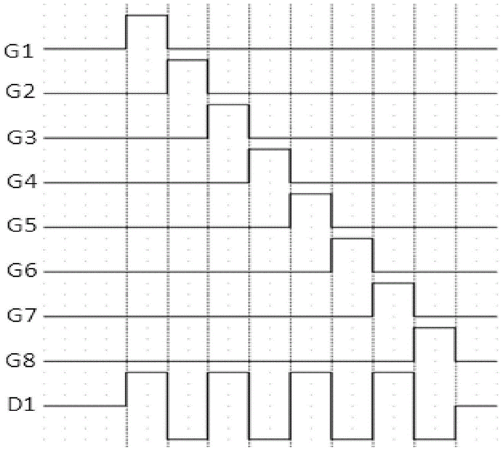
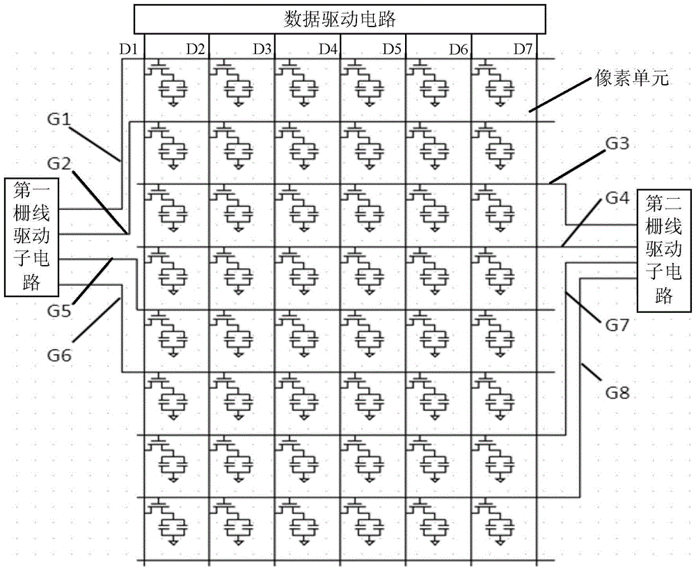
[0034] Embodiment 1 of the present invention provides a polarity inversion driving method, which is used to drive an array substrate. Wherein, the array substrate includes: a base substrate and gate lines and data lines formed on the base substrate, the gate lines and data lines define pixel units, the gate lines include: first gate lines and second gate lines, and a plurality of first gate lines One grid line and multiple second grid lines are arranged alternately. Then the polarity inversion driving method includes: when a frame is displayed, turn on the pixel units corresponding to the first gate line sequentially through the first gate line, load the first data voltag...


PUM


Abstract

A polarity-reversal driving method comprises: when a picture is displayed, sequentially connecting pixel units corresponding to a first gate line by using a first gate line, loading first data voltage signals to the connected pixel units by using odd-numbered columns of data lines, and loading second data voltage signals to the connected pixel units by using even-numbered columns of data lines, polarities of the first data voltage signals being opposite to those of the second data voltage signals; and sequentially connecting pixel units corresponding to a second gate line by using a second gate line, loading third data voltage signals to the connected pixel units by using odd-numbered columns of data lines, and loading fourth data voltage signals to the connected pixel units by using even-numbered columns of data lines, polarities of the third data voltage signals being opposite to those of the fourth data voltage signals. The polarity-reversal driving method reduces the number of times of the polarity reversal, thereby reducing the power consumption of a display panel. Also disclosed is a polarity-reversal driving circuit.

Description

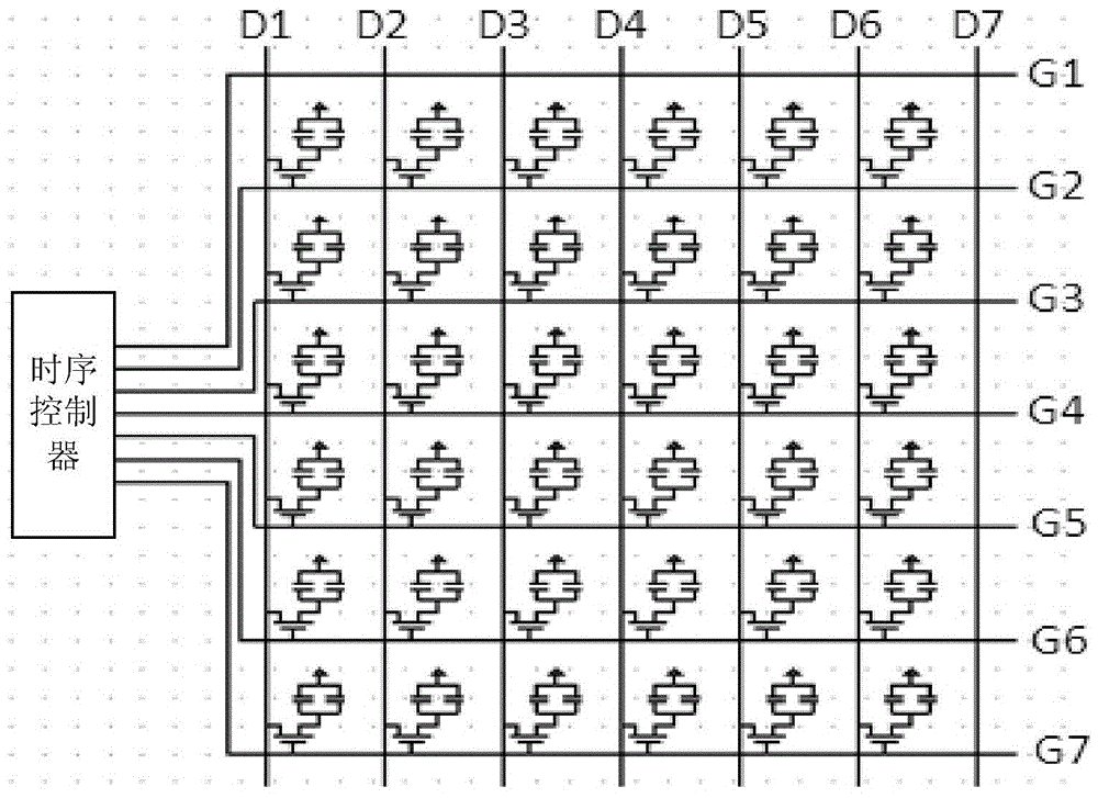
technical field [0001] The invention relates to the field of display technology, in particular to a polarity inversion driving method and a polarity inversion driving circuit. Background technique [0002] A liquid crystal display is a commonly used flat panel display at present, and a thin film transistor liquid crystal display (Thin Film Transistor Liquid Crystal Display, TFT-LCD for short) is a mainstream product in the liquid crystal display. Array substrates are important components of liquid crystal displays. The array substrate includes: a base substrate and gate lines and data lines formed on the base substrate, and the gate lines and data lines define pixel units. figure 1 It is a schematic diagram of a pixel unit array of an array substrate in the prior art, such as figure 1 As shown, the gate lines G1 to G7 and the data lines D1 to D7 define a plurality of pixel units, and the gate lines G1 to G7 are all connected to the timing controller. The timing controller...

Claims


Application Information

Patent Timeline
Patent Type & Authority Patents(China)
IPC IPC(8): G09G3/36
CPCG09G3/3614G09G3/3648G09G2330/021
Inventor 秦锋姜清华李小和
Owner HEFEI BOE OPTOELECTRONICS TECH
Learn More