Led lighting unit

A technology of LED lighting and wires, which is applied to lighting devices, lighting and heating equipment, and parts of lighting devices. It can solve the problems of adding parts and complicated assembly work, and achieve the effect of easy installation.

Inactive Publication Date: 2013-12-18
YAZAKI CORP
View PDF8 Cites 0 Cited by
  • Summary
  • Abstract
  • Description
  • Claims
  • Application Information

AI Technical Summary

Problems solved by technology

Therefore, a large number of parts are added, and assembly work becomes complicated

Method used


Image

  • Led lighting unit
  • Led lighting unit
  • Led lighting unit

Examples


Embodiment Construction

[0088] An LED lighting unit according to an embodiment of the present invention will be described in detail with reference to the accompanying drawings.

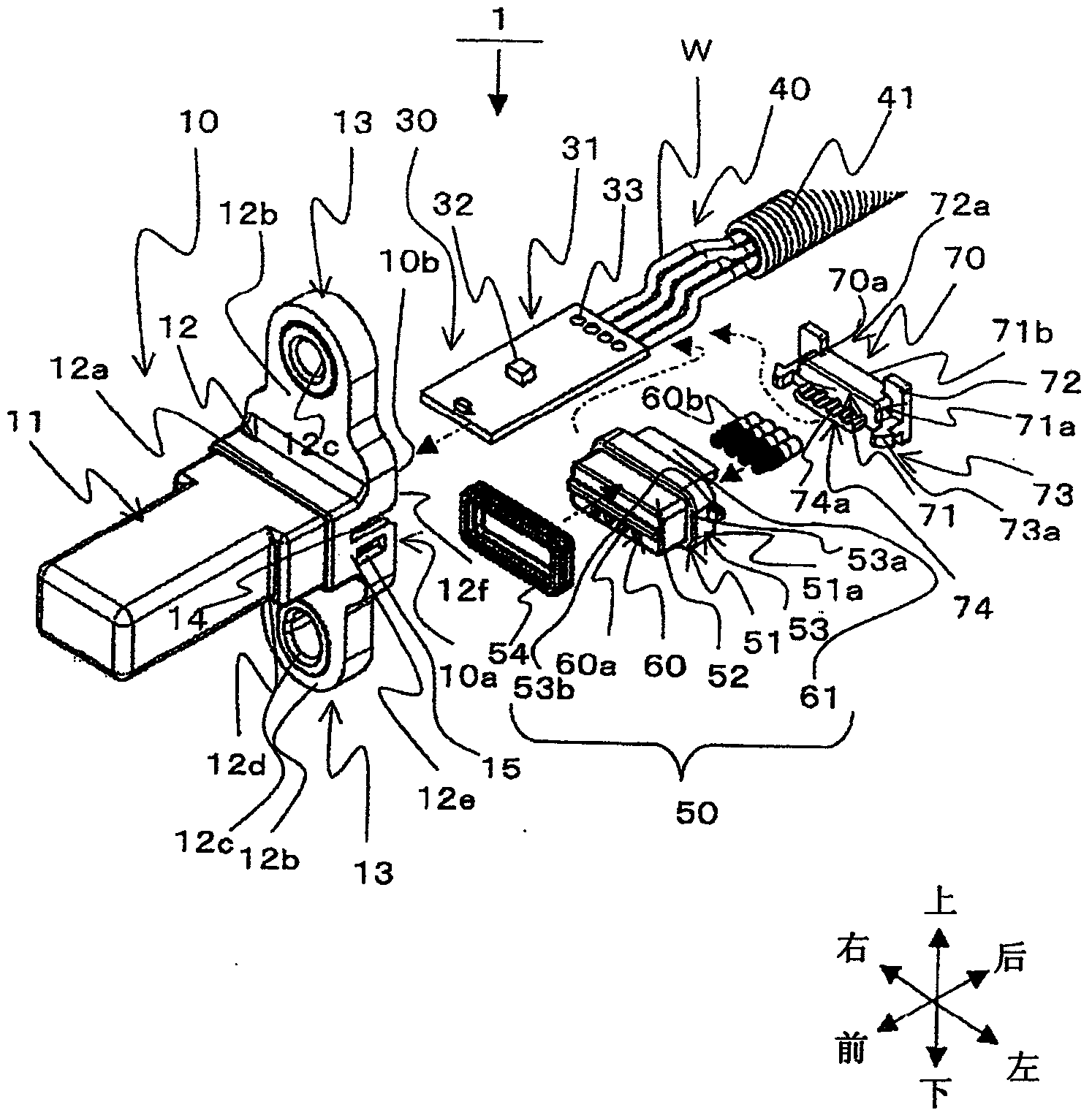
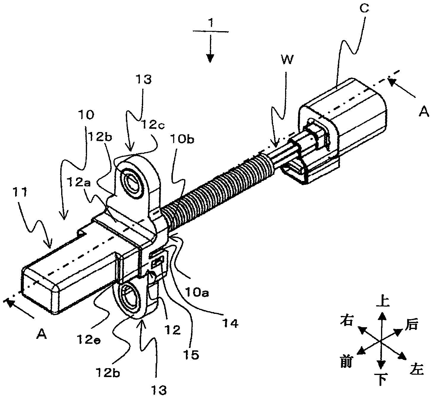
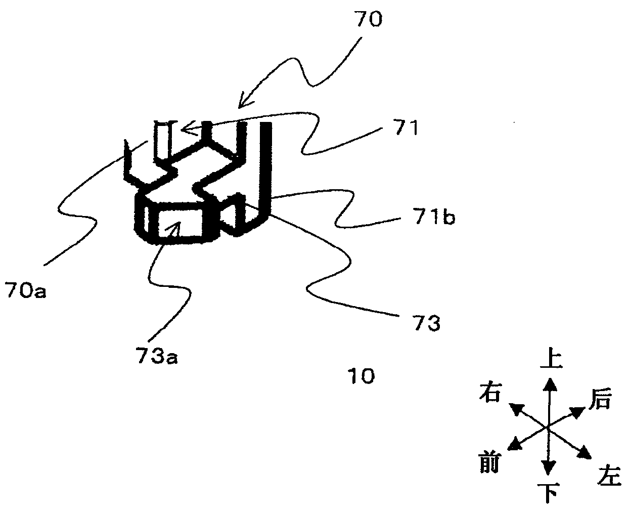
[0089] figure 1 is an exploded perspective view of the LED lighting unit 1 according to the embodiment of the present invention. figure 2 is showing figure 1 A perspective view of the shown LED lighting unit 1 and the connector C connected to the LED lighting unit 1 . Figure 3A with 3B yes figure 1 An enlarged view of the main part of the housing 10 and the holder 70 is shown. Figure 4 is showing figure 1 A schematic diagram of the outer periphery of the assembly surface B2 of the body B to which the LED lighting unit 1 is assembled is shown.

[0090] For convenience, in the drawings, it is assumed that the directions of mutually perpendicular arrows are the directions of front, rear, left, right, up and down.

[0091] The LED lighting unit 1 includes a housing 10 , an LED lighting portion 30 , a harness portion 40...


PUM


Abstract

An LED lighting unit (1) includes a housing (10), a circuit board (31) and a seal member (50). The seal member includes a seal main body (51) inserted into the housing in an insertion direction, a wire insertion portion (60), a protrusion piece (61) protruded from a rear surface of the seal main body opposite to the insertion direction. A holder (70) is arranged at one side of an opening of the housing relative to the seal member and includes a guide base (71) inserted into the housing, a protruded wire guide portion (74) protruded from a front end surface of the guide base and arranged at a position facing the wire insertion portion within the housing, and a wire lead portion (72a) leading an electric wire from a position adjacent to the guide base to the external. The opened surface of the housing coincides with a rear end surface of the guide base within the housing.

Description

technical field [0001] The invention relates to an LED lighting unit in which a circuit board on which LED (Light Emitting Diode) elements are installed is accommodated in a casing. Background technique [0002] A circuit board having LED (Light Emitting Diode) elements mounted thereon is housed in the LED lighting unit in the case, and while maintaining waterproofness, wires having one end connected to the circuit board are led out from the opening of the case. Thus, a sealing material that maintains waterproofness within the housing is required to lead out the contents of the housing. Therefore, a large number of parts are added, and the assembly work becomes complicated. In this case, for example, Patent Document 1 proposes a crimp terminal fixing structure of a crimp connector and a seal that securely fix the crimp terminal and the seal in a block. [0003] reference list [0004] patent documents [0005] Patent Document 1: JP-A-2004-356013 Contents of the inventi...

Claims


Application Information

Patent Timeline
Patent Type & Authority Applications(China)
IPC IPC(8): F21V27/02F21V31/00
CPCF21V27/02F21V31/005F21Y2115/10F21V31/00
Inventor 泽柳昌広
Owner YAZAKI CORP
Why Eureka
Try Eureka