Textile cleaner

A cleaner and shell technology, applied in the textile field, can solve the problems of increasing production profit, unfavorable sustainable development, waste of resources, etc., and achieve the effects of improving production profit, facilitating cleaning work, and saving resources

Inactive Publication Date: 2013-12-25
CHANGSHU FANGYUAN TEXTILE EQUIP FACTORY
View PDF9 Cites 6 Cited by
  • Summary
  • Abstract
  • Description
  • Claims
  • Application Information

AI Technical Summary

Problems solved by technology

[0003] Although there are many types of textile cleaners on the market, there are still some shortcomings. For textile mills, text

Method used


Image

  • Textile cleaner

Examples


Embodiment Construction

[0012] In order to make the technical means, creative features, goals and effects achieved by the present invention easy to understand, the present invention will be further described below in conjunction with specific embodiments.

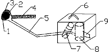
[0013] Such as figure 1 As shown in and, a textile cleaner includes a first housing 6, a second housing 3, a telescopic rod 4 and a conduit 5, and the conduit 5 is connected to the first housing 6 and the second housing 3, and the first housing 6 is connected to the second housing 3. A housing 6 is provided with a content device 8 and an aspirator 7, the content device 8 is provided with an outlet 9, the second housing 3 is provided with an inlet 1, and the inlet 1 is a circle with a diameter of 10-20cm, and the second shell 3 is connected with the telescopic rod 4.

[0014] It is worth noting that the conduit 5 is made of polyethylene plastic material, and the conduit has good stretchability and is easy to clean.

[0015] In this embodiment, th...


PUM

PropertyMeasurementUnit
Diameteraaaaaaaaaa

Abstract

The invention discloses a textile cleaner and relates to the textile field. The textile cleaner comprises a first casing, a second casing and a guide pipe; the guide pipe is connected with the first casing and the second casing; an object accommodating device and an air suction device are arranged in the first casing; the object accommodating device is provided with the object outlet; the second casing is provided with the object inlet which is circular; the diameter of the object inlet is 10 to 20 cm. Objects such as flying catkins and dust can be sucked into the textile cleaner through the object inlet, the dust which is sucked in can be adsorbed through a dust collecting net, and the flying catkins enter into the object accommodating device, so that the textile cleaner has the advantages of enabling textiles such as the flying catkins to be recycled and reused, being capable of saving resources well, being beneficial to sustainable development and increase of productive profits and meanwhile achieving the cleaning purpose.

Description

technical field [0001] The invention relates to the textile field, in particular to a textile cleaner. Background technique [0002] With the development of science and technology, the textile industry is also developing rapidly. Science and technology serve the people, and various machinery and equipment related to the textile industry emerge in endlessly. The patent application number 201220615562.3 discloses a textile cleaner, which is characterized in that it includes: a handle, a battery and a drive motor arranged in the handle, a rotating rod fixedly connected to the driving motor; The cross-section of the wadding section is 8-shaped; the cross-section of the connecting section of the aforementioned rotating rod located in the handle is circular; the aforementioned rotating rod is a carburized steel needle; the aforementioned handle is cylindrical, and the surface is provided with a non-slip grip glue. The invention is beneficial in that: the cross-section of the wad...

Claims


Application Information

Patent Timeline
IPC IPC(8): B08B5/04
Inventor 王振芳
Owner CHANGSHU FANGYUAN TEXTILE EQUIP FACTORY
Why Eureka
Try Eureka