
Six-degree-of-freedom humanoid robot arm

A humanoid robot with degrees of freedom technology, applied in the field of robot arms, can solve the problems of bloated joint structure of robot arm, heavy weight, complicated control, etc., and achieve the effect of simple shoulder joint rotation structure, simple structure and high transmission precision

Active Publication Date: 2015-07-22
HARBIN INST OF TECH
View PDF6 Cites 1 Cited by
  • Summary
  • Abstract
  • Description
  • Claims
  • Application Information

AI Technical Summary

Problems solved by technology

[0003] The purpose of the present invention is to solve the problems of the existing robot arm with bloated joint structure, large self-weight, small load-to-weight ratio and cumbersome control

Method used


Image

  • Six-degree-of-freedom humanoid robot arm
  • Six-degree-of-freedom humanoid robot arm
  • Six-degree-of-freedom humanoid robot arm

Examples


specific Embodiment approach 1

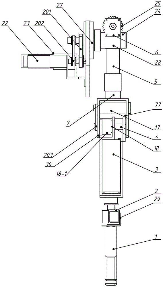
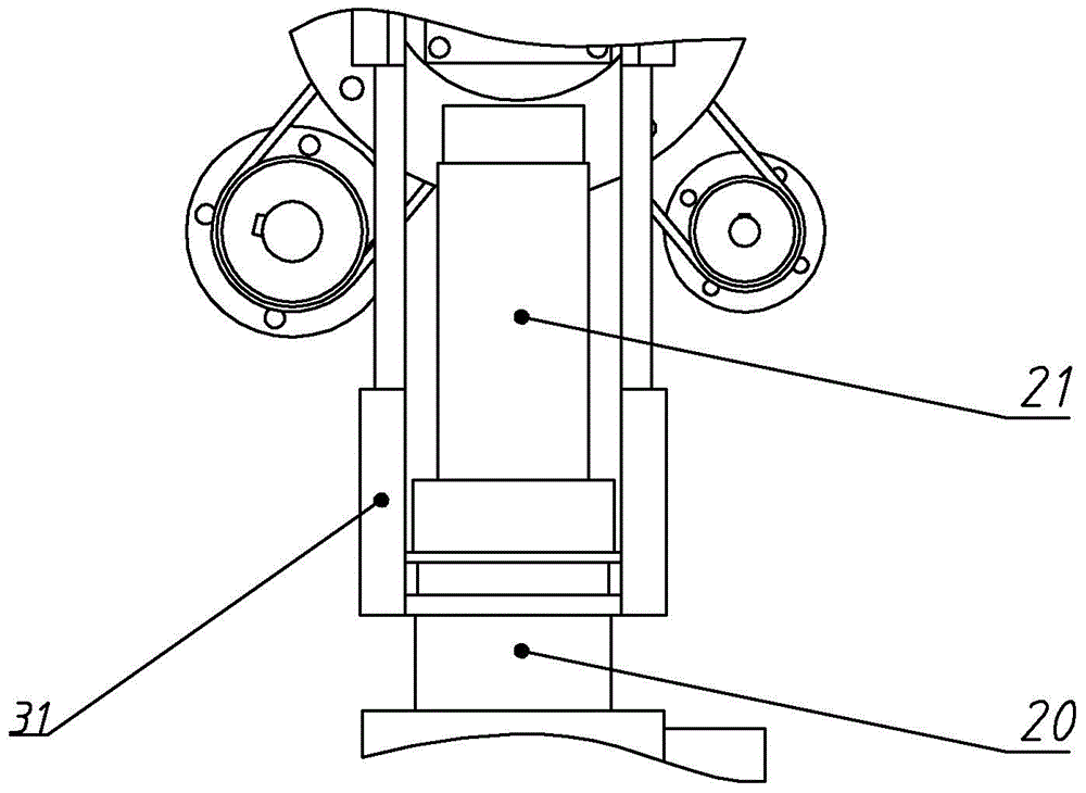
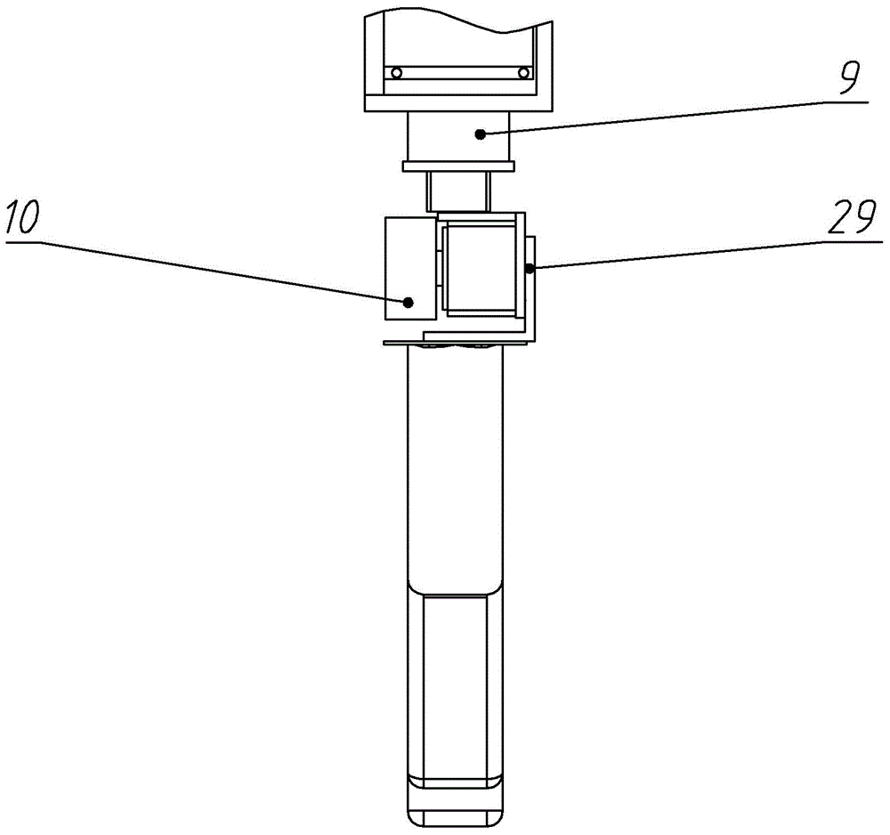
[0020] Specific implementation mode one: combine Figure 1-Figure 6 Describe this embodiment, this embodiment includes claw 1, wrist joint 2, forearm 3, elbow pendulum joint 18, elbow joint 77, big arm 5 and shoulder joint 6, shoulder joint 6, big arm 5, elbow joint 77, Forearm 3, wrist joint 2 and hand claw 1 are arranged in sequence from top to bottom,

[0021] Described shoulder joint 6 comprises swing arm servo motor 22, swing arm servo motor 23, rotating conveyor belt 201, swing arm conveyor belt 202, shoulder swing support 27, worm gear 25, worm screw 24 and shoulder joint support 28, shoulder swing support 27 and Shoulder joint support 28 is fixedly arranged successively from left to right, and rotation conveyor belt 201 and swing arm conveyor belt 202 are arranged on the left side of shoulder lifting and shoulder swing support 27, and worm gear 25 and worm screw 24 are arranged on shoulder joint support 28, and worm gear 25 and the worm screw 24 mesh with each other, ...

specific Embodiment approach 2

[0031] Specific implementation mode two: combination figure 1 The present embodiment is described. The elbow joint drive motor 17 of the elbow joint drive motor 4 in this embodiment is horizontally arranged in the elbow joint housing 30 and connected to the elbow joint conveyor belt 203 . Such setting saves space and reduces the driving load on the shoulder. Other compositions and connections are the same as in the first embodiment.

specific Embodiment approach 3

[0032] Specific implementation mode three: combination figure 1 The present embodiment will be described. Both the wrist joint swing motor 10 and the wrist joint rotation motor 9 in this embodiment are disk motors. With such arrangement, the volume is small, the space is saved and the terminal payload is improved. Other compositions and connections are the same as those in the second embodiment.


PUM


Abstract

The invention discloses a six-degree-of-freedom humanoid robot arm, and relates to a robot arm. The invention aims to solve the problems that the existing robot arm is cumbersome in joint structure, heavy in self weight, low in load bearing ratio and complicated to control. A shoulder rotating joint, a shoulder joint, an upper arm, an elbow rotating joint, a elbow swing joint, a fore arm, a wrist rotating joint, a wrist swing and a hand are sequentially arranged from top to bottom, wherein an arm swing motor is connected with a worm by virtue of a conveyor belt, an arm rotating motor is connected with a shoulder swing support by virtue of a conveyor belt, an upper arm shell is arranged between a shoulder joint and an elbow joint, an elbow rotating drive motor and a speed reducer are sequentially arranged in the upper arm shell from top to bottom, an elbow swing joint motor is arranged in an elbow joint shell and is connected with an elbow joint conveyor belt, an elbow joint speed reducer is arranged in the elbow joint shell, a hand connecting support is arranged between the fore arm and the hand, a wrist joint swing motor is arranged on one side of the hand connecting support, and a wrist joint rotating motor is arranged at the upper end of the hand connecting support. The six-degree-of-freedom humanoid robot arm is applied to a humanoid robot.

Description

technical field [0001] The invention relates to a robot arm, in particular to a six-degree-of-freedom humanoid robot arm. Background technique [0002] With the advancement of science and technology, the research and application fields of robots are constantly expanding. Among them, the research and application of humanoid robots have received widespread attention and become one of the most active research hotspots in the field of intelligent robots. Humanoid robots are widely used in the fields of helping the elderly and the disabled, and can complete actions such as taking medicine, pouring water, fetching items from the refrigerator, opening doors, and helping the elderly. The robot arm is the most representative complex part in the humanoid robot system. It is the basis for the humanoid robot to complete the grasping operation and interact with the human machine. The humanoid robot is equipped with dual arms, so its compact structure design and versatility Flexibility i...

Claims


Application Information

Patent Timeline
Patent Type & Authority Patents(China)
IPC IPC(8): B25J18/00B25J17/00
Inventor 李瑞峰赵立军梁培栋马国庆张腾飞仝勋伟
Owner HARBIN INST OF TECH
Learn More