Concrete chimney dismantling method

A technology for chimneys and operating platforms, applied to building types, buildings, towers, etc., can solve problems such as unsatisfactory construction progress, low work efficiency, and large engineering volume, and achieve simple and easy-to-operate demolition methods, high work effects, and avoid waste Effect

Active Publication Date: 2015-06-10
CHINA 22MCC GROUP CORP
View PDF6 Cites 0 Cited by
  • Summary
  • Abstract
  • Description
  • Claims
  • Application Information

AI Technical Summary

Problems solved by technology

[0002] The traditional demolition method of high-rise brick-concrete buildings is blasting or impact. This traditional demolition method is not only dangerous, but also destructive. Once the force is not well controlled, it may cause damage to other buildings.
[0003] At present, the staged demolition method can also be adopted for brick-concrete high-rise buildings, but it needs to build a high scaffold as an operating platform, which requires a large amount of work and serious waste of materials, and this staged demolition method is mostly suitable for square or round buildings. tubular building
However, the demolition of towering buildings with conical barrel structures such as chimneys is more difficult, especially the demolition of concrete chimneys. The conventional demolition method has a long construction period and low work efficiency, which cannot meet the construction progress.

Method used


Image

  • Concrete chimney dismantling method
  • Concrete chimney dismantling method
  • Concrete chimney dismantling method

Examples


Embodiment Construction

[0041] The present invention will be further described below in conjunction with the accompanying drawings and embodiments.

[0042] The invention firstly discloses a device for removing a concrete chimney, and secondly discloses a method for removing a concrete chimney by using the device.

[0043] The removal device includes a positioning mechanism, an operating platform and a hoisting mechanism.

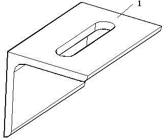
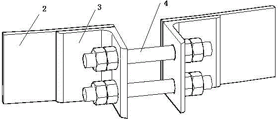
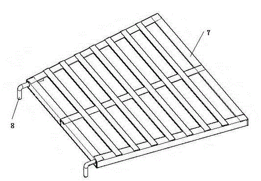
[0044] The positioning mechanism includes a hoop 2, a connecting head 3 and a hanging ear 1. The hoop is a circular structure composed of multiple arc-shaped plates, such as image 3 As shown, the preferred number of initial segments is two, and connectors are provided at the interface of adjacent arc-shaped plates. A plurality of hanging ears are uniformly arranged on the outer wall of the hoop. In this example, if figure 2 As shown, the connector includes two angle steels respectively fixed at the free ends of the hoop interface, one side of which is fixed to the outer ...


PUM


Abstract

The invention discloses a concrete chimney dismantling device. The concrete chimney dismantling device comprises a positioning mechanism, an operation platform and a hoisting mechanism; the positioning mechanism comprises a hoop, connectors and hanging lugs; the hoop is of a ring structure constructed by multiple segments of arc-shaped plates, one connector is arranged on the interface of each segment of arc-shaped plate, and multiple hanging lugs are uniformly arranged on the outer wall of the hoop; the operation platform comprises a trapezoidal platform, hooks and handrails, diagonal braces are arranged at the bottom of the trapezoidal platform, the hooks and the handrails are respectively and fixedly connected with the two sides of the trapezoidal platform, the handrails and the trapezoidal platform are arranged vertically, and the hooks are matched with the hanging lugs; the hoisting mechanism comprises a hoisting rope, a clamping apparatus and a hoisting tool, the hoisting rope is fixedly arranged on the hoop, the clamping apparatus is fixedly mounted on the side wall of a concrete chimney, and the hoisting rope, the clamping apparatus and the hoisting tool are used in a matched manner. The concrete chimney dismantling device has the advantages that the structure is simple, the dismantling device can be fabricated by waste material in a construction site, the cost is low, the dismantling device can be used repeatedly, and the waste of material is avoided; a dismantling method provided by the invention has the advantages that the method is simple, the operation is easy, the safety is high, buildings around the concrete chimney cannot be destroyed, and the working effect is good.

Description

technical field [0001] The invention relates to a device and method for dismantling a brick-concrete towering building, in particular to a device and method for dismantling a concrete chimney. Background technique [0002] The traditional demolition method of brick-concrete towering buildings is blasting or impact. This traditional demolition method is not only dangerous, but also destructive. Once the force is not well controlled, it may cause damage to other buildings. [0003] At present, the staged demolition method can also be adopted for brick-concrete high-rise buildings, but it needs to build a high scaffold as an operating platform, which requires a large amount of work and serious waste of materials, and this staged demolition method is mostly suitable for square or round buildings. Tubular buildings. And the demolition difficulty of towering buildings with conical barrel structures such as chimneys is relatively large, especially the demolition of concrete chimne...

Claims


Application Information

Patent Timeline
Patent Type & Authority Patents(China)
IPC IPC(8): E04H12/34
Inventor 吴长德刘宗辉
Owner CHINA 22MCC GROUP CORP
Why Eureka
Try Eureka