
Pressurizing device

A technology of a booster device and a booster cylinder, which is applied in the hydraulic field and can solve problems such as a small booster ratio

Active Publication Date: 2014-09-10
SHANDONG UNIV OF SCI & TECH
View PDF1 Cites 2 Cited by
  • Summary
  • Abstract
  • Description
  • Claims
  • Application Information

AI Technical Summary

Problems solved by technology

The disadvantage is that under the same volume, the boost ratio is small

Method used


Image

  • Pressurizing device
  • Pressurizing device
  • Pressurizing device

Examples


Embodiment Construction

[0048] The invention will be described in detail below in conjunction with the accompanying drawings.

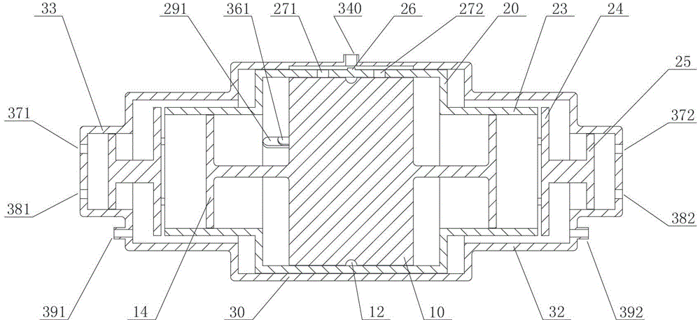
[0049] Such as figure 1 As shown, a booster cylinder includes three parts: a primary piston 10, a secondary piston 20 and a cylinder barrel 30. The primary piston 10 is set in the inner cavity of the secondary piston 20, and the secondary piston 20 is set in the cylinder barrel 30. The inner chamber of the first stage piston 10 and the second stage piston 20 move with each other to complete the first pressurization of the hydraulic oil; the relative movement of the second stage piston 20 and the cylinder barrel 30 completes the second pressurization of the hydraulic oil.

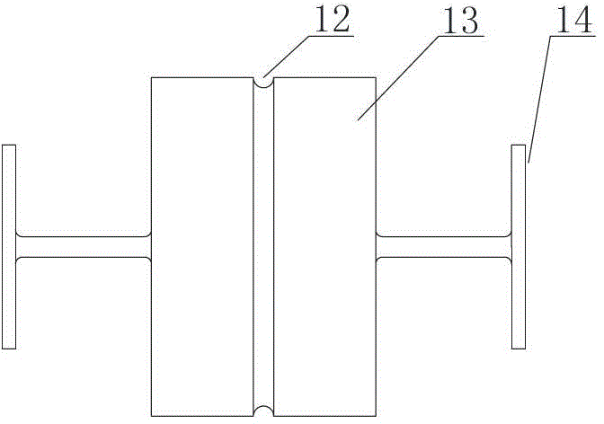
[0050] Such as figure 2 As shown, the primary piston 10 includes a main body, the main body is a cylinder 13 with an annular groove 12 on the circumferential surface, and a disc 14 is respectively formed on the two ends of the cylinder 13, the circle Area A of disc 14 14 less than the cross-sectional a...


PUM


Abstract

The invention provides a pressurizing device. The pressurizing device comprises a pressurizing cylinder and an integrated valve block, wherein the pressurizing cylinder comprises a primary piston (10), a secondary piston (20) and a cylinder tube (30), the primary piston (10) is sleeved in an inner cavity of the secondary piston (20), and the secondary piston (20) is sleeved in an inner cavity of the cylinder tube (30); the integrated valve block comprises a valve body (200), the valve body (200) is provided with an inner cavity (201), the valve body (200) is respectively provided with a through hole at two ends of the inner cavity (201), five annular through holes are radially arranged between the wall surface of the outer wall and the inner cavity (201) of the valve body (200), the inner cavity (201) is internally sleeved with a valve core (220), and a zero-opening two-position four-way reversing valve is formed in a way that the valve core (220) is matched with the inner cavity (201). Compared with a pressurizing device in the prior art, the pressurizing device provided by the invention is small in size, has no participation of an electric control system and is simple in system.

Description

technical field [0001] The invention belongs to the technical field of hydraulic pressure and relates to a supercharging device, in particular to a supercharging cylinder, an integrated valve block and a supercharging device thereof. Background technique [0002] The principle of the pressurized cylinder in the general sense is to increase the proportional output of the input hydraulic oil according to the difference in the effective area of ​​the piston and the plunger. The boost ratio is equal to the inverse ratio of the piston area. This booster cylinder only performs one-stage booster conversion, and the booster ratio is a linear proportional relationship between the radial area of ​​the piston and the plunger, and does not fully utilize the space volume of the booster cylinder for boosting. In order to achieve two-way continuous supercharging, the following double-acting reciprocating superchargers have emerged, such as electromagnetic reversing valves, etc. However, ...

Claims


Application Information

Patent Timeline
Patent Type & Authority Patents(China)
IPC IPC(8): F15B3/00F15B15/14
Inventor 曾庆良刘继龙万丽荣张鑫刘志海王成龙王亮赵吉龙王天超苏兴明
Owner SHANDONG UNIV OF SCI & TECH
Learn More