Bird-like wing-shaped multi-channel groove end face sealing structure

An end-face sealing, multi-channel technology, applied in the direction of engine sealing, engine components, mechanical equipment, etc., can solve the problems of unsatisfactory resistance to external disturbance, large leakage rate, poor starting or stopping performance, etc., and achieve excellent comprehensive sealing performance , Improve the bearing capacity and reduce the effect of leakage

Active Publication Date: 2016-08-10
ZHEJIANG UNIV OF TECH
View PDF14 Cites 2 Cited by
  • Summary
  • Abstract
  • Description
  • Claims
  • Application Information

AI Technical Summary

Problems solved by technology

The above-mentioned dry gas end seals generally have poor start-up or stop performance, large leakage rate or unsatisfactory resistance to external disturbances, and it is difficult to meet special operating requirements such as low speed and frequent start-up.

Method used


Image

  • Bird-like wing-shaped multi-channel groove end face sealing structure
  • Bird-like wing-shaped multi-channel groove end face sealing structure
  • Bird-like wing-shaped multi-channel groove end face sealing structure

Examples


Embodiment 1

[0029] see figure 1 , Figure 2 and image 3 ,

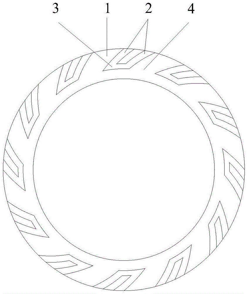
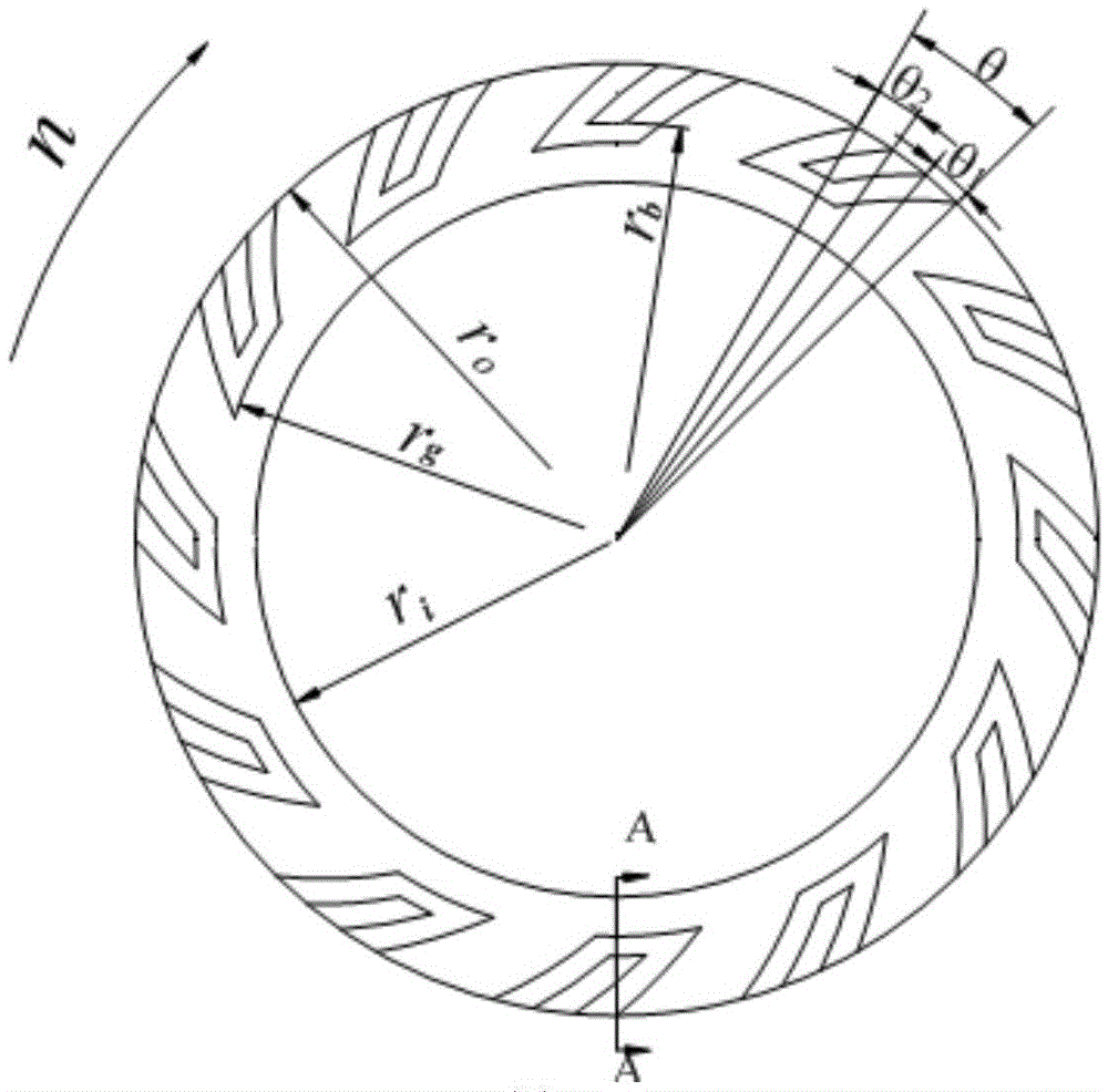
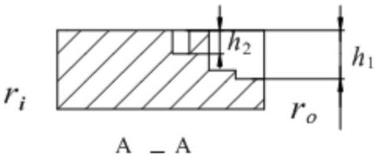
[0030] In this example, a bird-wing-shaped multi-channel end face seal structure includes two mechanical seal rings, that is, a moving ring and a static ring. There are a plurality of imitation bird-wing multi-pass grooves evenly distributed along the circumference, and the imitation bird-wing multi-pass grooves are located on the high-pressure side of the medium, that is, upstream; the imitation bird-wing multi-pass grooves include more than two drainage grooves 2 and One or more arc grooves 3, the arc groove 3 is located on the downstream side of the drainage groove 2 and connected with each drainage groove 2, the drainage groove 2 communicates with the outer diameter of the sealing ring, the two or more The drainage grooves 2 are distributed along the circumferential direction, and the sealing weirs 1 without slots are used to isolate the drainage grooves 2. The annular zone formed by the non-grooving area on the upper surfa...

Embodiment 2

[0037] see Figure 4 The difference between this embodiment and Embodiment 1 is that the drainage groove 2 is a double-row connected spiral groove, the direction of the helix angle of the upstream spiral groove 2a is opposite to that of the downstream spiral groove 2b, and the downstream spiral groove 2b and the downstream spiral groove 2b are opposite to each other. The circular arc grooves 3 are connected, and the rest of the structure and implementation are the same as in the first embodiment.

Embodiment 3

[0039] see Figure 5 , the difference between this embodiment and embodiment one is that the number N of the drainage grooves y =3, the three drainage grooves are distributed along the circumferential direction, and the number of arc grooves N h =2, the arc grooves are distributed along the radial direction, the middle drainage groove 2c and the leeward side drainage groove 2a are connected through the upstream arc groove 3a, the middle drainage groove 2c is not connected with the downstream arc groove 3b, and the rest of the structure And the embodiment is the same as the first embodiment.


PUM


Abstract

A bird-wing-shaped multi-channel groove end face seal structure, including a moving ring and a static ring of a mechanical seal, at least one sealing ring of the moving ring or the static ring is provided with a plurality of bird-wing-shaped multi-channels evenly distributed along the circumference The bird-wing multi-channel groove is located on the high-pressure side of the medium, that is, the upstream; the bird-like multi-channel groove includes two or more drainage grooves and one or more arc grooves, and the arc groove is located The downstream side of the drainage groove is connected with the drainage groove. The drainage grooves are connected with the medium high pressure side or the upstream and are evenly distributed along the circumference. The drainage grooves are separated by sealing weirs without slots; the end surface The annular zone formed by the ungrooved area in the circumferential direction is a sealing dam, which is located on the low pressure side of the end face, ie downstream. The invention has strong end face static pressure effect, low power consumption, good running stability at low speed, small leakage and excellent anti-interference performance, and is especially suitable for non-contact dry gas seal end face sealing devices for equipment such as reaction kettles and agitators. .

Description

technical field [0001] The invention relates to a bird-wing-shaped multi-channel groove end face sealing structure, which belongs to a non-contact dry gas sealing device for a rotating shaft, and is suitable for the shaft end sealing device for rotating shafts of various compressors, pumps, kettles and other rotating equipment. Background technique [0002] The shafts of rotary fluid mechanical equipment generally adopt ordinary mechanical seals or non-contact end face seals. In the late 1970s, the sealing technology began to be partially replaced by the dry gas seal of "gas seal liquid" or "gas seal gas". The above-mentioned ordinary contact or non-contact liquid lubricated mechanical seals have achieved remarkable results, represented by John Crane (www.johncrane.com), Flowserve (www.flowserve.com) and Bergmann (www.eagleburgmann.com) The world-renowned sealing companies have successively developed one-way rotating dry gas seals such as spiral grooves, spiral grooves with...

Claims


Application Information

Patent Timeline
Patent Type & Authority Patents(China)
IPC IPC(8): F16J15/40
Inventor 彭旭东张风云白少先李纪云孟祥铠
Owner ZHEJIANG UNIV OF TECH
Why Eureka
Try Eureka