Vehicle locating method based on matching of road surface image characteristics

A vehicle positioning and image feature technology, applied in the field of image processing, can solve time-consuming and labor-intensive problems

Active Publication Date: 2013-12-25
CHANGAN UNIV
View PDF2 Cites 28 Cited by
  • Summary
  • Abstract
  • Description
  • Claims
  • Application Information

AI Technical Summary

Problems solved by technology

This method is characterized by high positioning accuracy, but it needs to do preparatory work in advance, that is, take street views in a

Method used


Image

  • Vehicle locating method based on matching of road surface image characteristics
  • Vehicle locating method based on matching of road surface image characteristics
  • Vehicle locating method based on matching of road surface image characteristics

Examples


Embodiment 1

[0173] In this implementation, a digital CCD camera modeled as SONY XCI-SX100C was installed vertically directly under the vehicle to capture road images in real time, and a 6-meter-long straight road section at the entrance of the School of Information, Chang’an University was selected as a test, shooting 30 frames per second; A total of 279 frames of road images were converted from the video, and the image size is 1280*960.

[0174] The uniform light processing is performed on the currently captured two consecutive frames of road surface images in sequence. The effect of a certain frame image after uniform light processing is as follows: figure 2 shown.

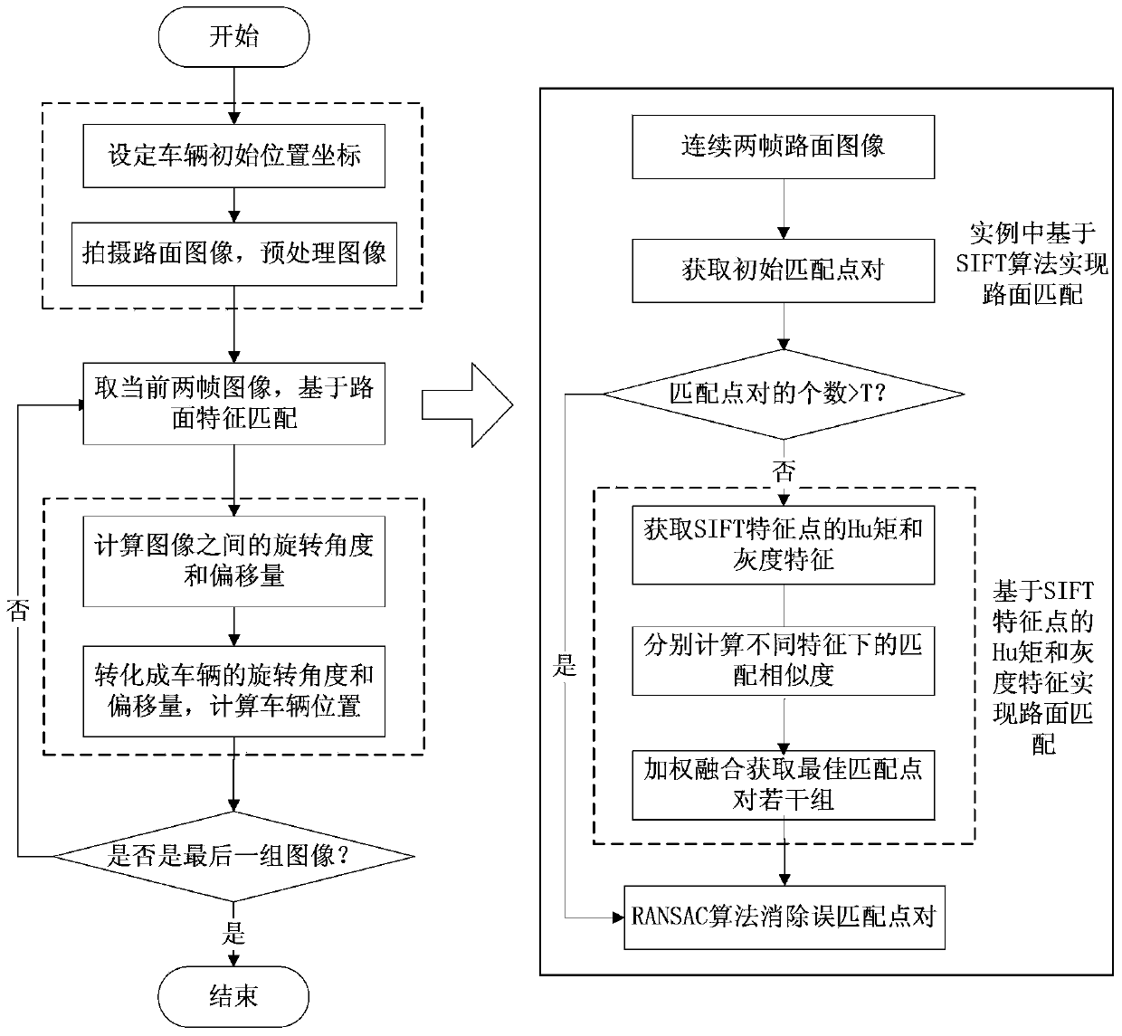
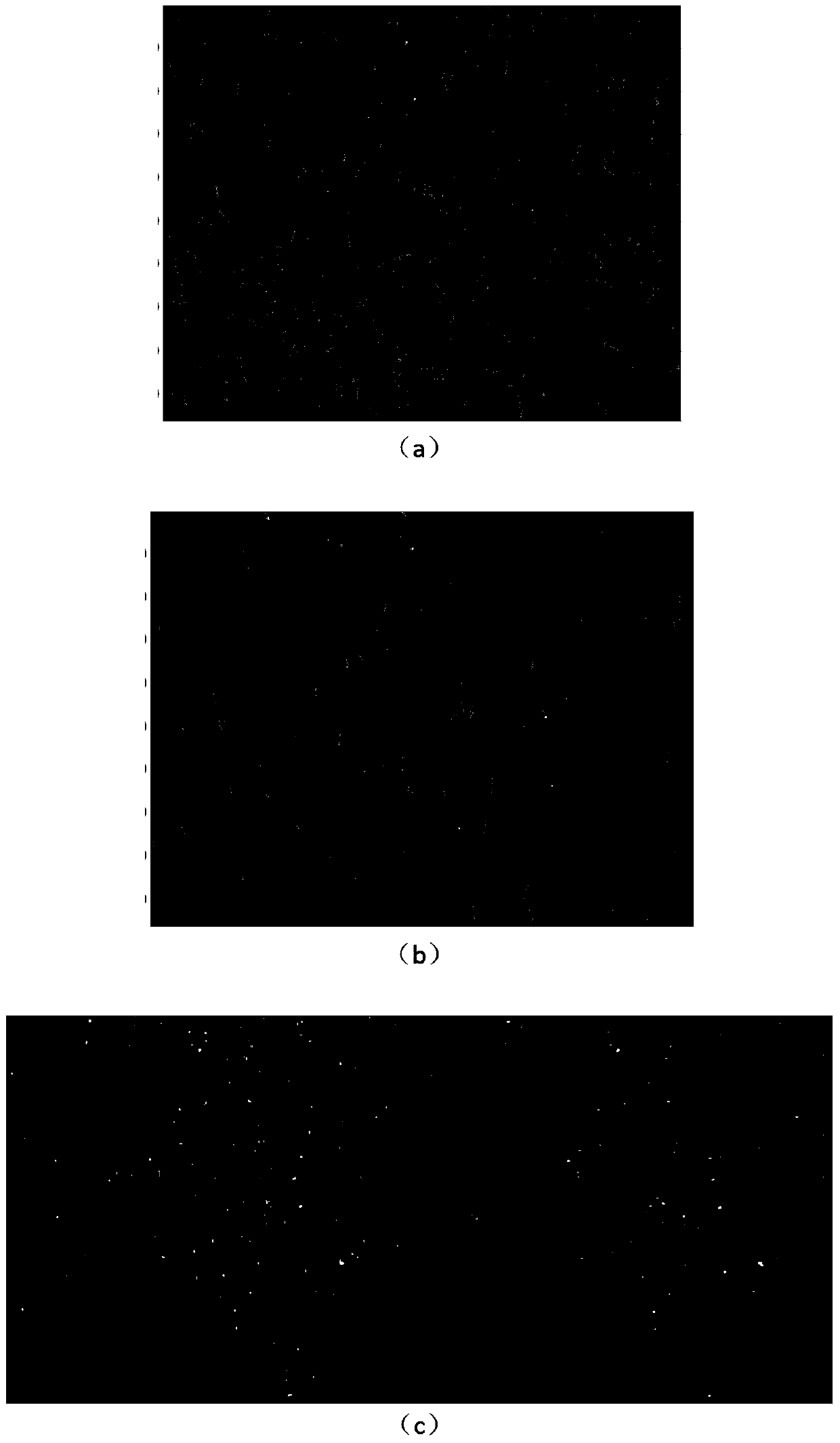
[0175] During the driving process of the vehicle, the captured road surface images are matched in real time, Figure 3-Figure 5 It is the rendering of road surface matching based on SIFT algorithm. When the SIFT algorithm is used, there are 42 groups of images (two consecutive frames of road images) where the number of m...

Embodiment 2

[0184] In this embodiment, a digital CCD camera modeled as SONY XCI-SX100C is vertically installed directly below the vehicle to take real-time images of the road surface, and a section of 12-meter-long turning section at the gate of the School of Information, Chang’an University is selected as a test, and a total of 682 Frame road image, the image size is 1280*960. The positioning process to the vehicle is the same as in embodiment 1, and the positioning track of the final vehicle operation is as follows Figure 9 (b) (the trajectory map of the vehicle running at the pixel level).

[0185] In summary, it can be seen that the method of the present invention realizes autonomous positioning based on road surface image matching, is not easily disturbed by the external environment, and has high accuracy.


PUM


Abstract

The invention discloses a vehicle locating method based on matching of road surface image characteristics. The vehicle locating method based on the matching of the road surface image characteristics comprises the steps of determining geographical coordinates of an initial position of a vehicle, shooting road surface images in real time in the traveling process of the vehicle, carrying out dogging processing on two shot current continuous frames of the road surface images in sequence, carrying out matching on the two continuous frames of the road surface images processed through the dogging in real time to obtain matching dot pairs of the two continuous frames of the road surface images, carrying out vehicle location on the vehicle according to the obtained matching dot pairs, judging whether the current two frames of the images are the last two frames or not, ending the process if the current two frames of the images are the last two frames, and otherwise repeating the steps. According to the vehicle locating method based on the matching of the road surface image characteristics, the road surface images only need to be collected in real time in the traveling process of the vehicle, and matching is carried out on the two continuous frames of the road surface images so that automatic vehicle location can be achieved; the method is not prone to interference, high in location precision and capable of saving time and labor due to the fact that the time-consuming and labor-consuming link of collecting all-dimensional street scenes in advance in an existing locating method is saved.

Description

technical field [0001] The invention belongs to the technical field of image processing, and in particular relates to a vehicle positioning method based on road surface image feature matching. Background technique [0002] Currently, commonly used vehicle positioning technologies include GPS positioning technology and inertial navigation (INS). GPS positioning technology is a passive positioning method, which has defects such as low positioning accuracy, signal blind area, and low output frequency. When the vehicle travels to a no-signal area, GPS cannot meet the requirements; The positioning accuracy cannot meet the requirements. Inertial Navigation (INS) is an autonomous positioning method that obtains the latitude, longitude and acceleration of the vehicle in real time during driving. It has the advantages of all-weather, anti-interference and high instantaneous measurement accuracy. However, its main component, the gyroscope, will drift over time. As a result, its posi...

Claims


Application Information

Patent Timeline
IPC IPC(8): G06T7/00
Inventor 赵祥模徐志刚周经美张立成程鑫任亮白国柱
Owner CHANGAN UNIV
Why Eureka
Try Eureka