LED lamp bead

A technology of LED lamp beads and accommodating cavity, which is applied in electrical components, electric solid-state devices, circuits, etc., can solve the problems of small heat dissipation area, color drift of LED lamp beads, and precipitation of phosphor powder, and achieve the effect of thin thickness

Inactive Publication Date: 2013-12-25
厦门市信达光电科技有限公司
View PDF4 Cites 3 Cited by
  • Summary
  • Abstract
  • Description
  • Claims
  • Application Information

AI Technical Summary

Problems solved by technology

Because the heat dissipation area of ​​the two pins 20 is too small, the temperature of the potting material resin colloid...

Method used


Image

  • LED lamp bead
  • LED lamp bead
  • LED lamp bead

Examples


Embodiment Construction

[0023] The present invention will be described in detail below in conjunction with the accompanying drawings and specific embodiments.

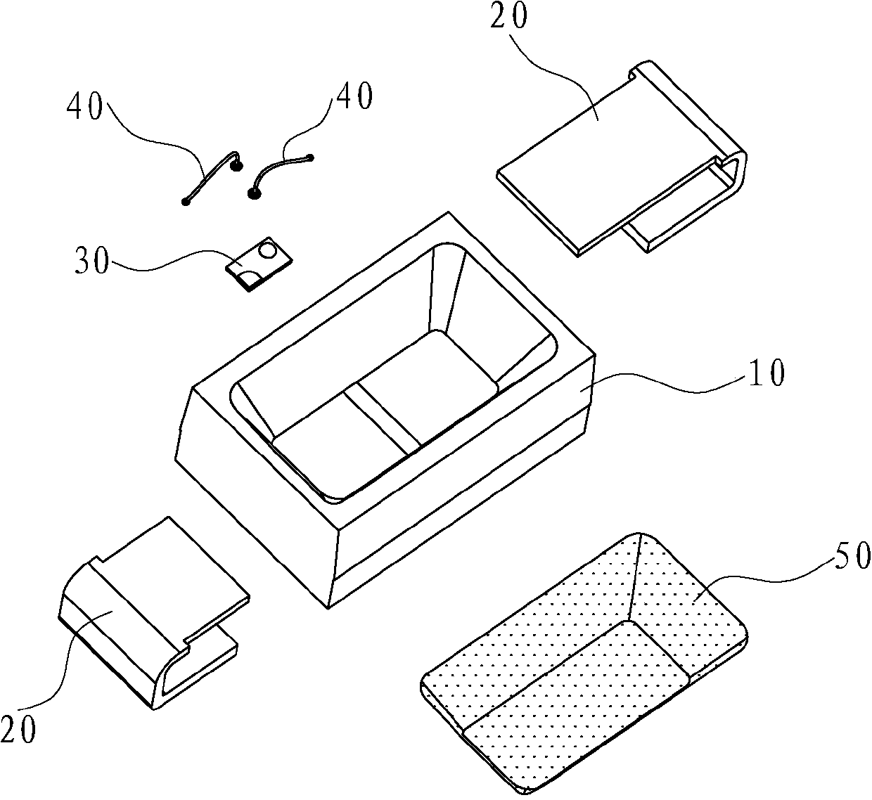
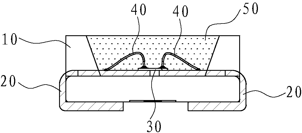
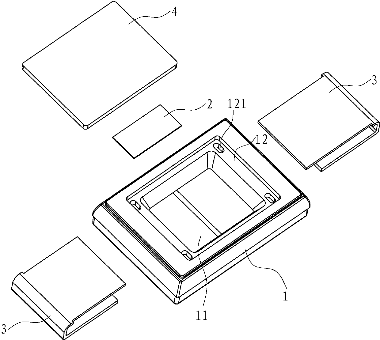
[0024] refer to Figure 3 to Figure 5 As shown, an LED lamp bead disclosed by the present invention includes a heat-conducting housing 1 provided with an accommodating cavity 11 , a flip chip 2 , two pins 3 and a fluorescent sheet 4 .

[0025] The two pins 3 are respectively embedded in the accommodating chamber 11 of the heat-conducting shell 1, and the bottom of the accommodating chamber 11 is sealed. The two pins 3 are respectively located on both sides of the heat-conducting shell 1. as the negative pole.

[0026] The flip chip 2 is mounted on the two pins 3 and is electrically connected to the two pins 3 respectively, that is, the flip chip 2 is electrically connected to the positive pin 3 and the negative pin 3 respectively, and the flip chip 2 is located in the container Put it in chamber 11.

[0027] The flip-chip 2 is mounted on t...


PUM


Abstract

The invention discloses an LED lamp bead which comprises a heat conduction shell provided with an accommodating cavity, a flip chip, a fluorescent sheet and two pins. The two pins are respectively embedded in the accommodating cavity of the heat conduction shell. The flip chip is mounted on the two pins in an attached mode, electrically connected with the two pins respectively, and located in the accommodating cavity. The fluorescent sheet is fixed on the heat conduction shell. According to the LED lamp bead, the technology of the heat conduction shell and the fluorescent sheet is adopted, a resin colloid does not need to be injected in the accommodating cavity to seal the accommodating cavity, therefore, the overall thickness of the LED lamp bead is small, the heat dissipation effect is good, and color drift cannot occur; a wire does not need to be welded to the flip chip, solid crystal glue does not need to be dotted on the flip chip, and therefore the LED lamp can be thinner.

Description

technical field [0001] The invention relates to an LED lamp bead. Background technique [0002] Such as figure 1 and figure 2 As shown, an LED lamp bead disclosed in the prior art includes a housing 10 with a housing cavity, two pins 20 , a chip 30 and two gold wires 40 ; the two pins 20 are symmetrically embedded in the housing cavity 10 , respectively located on both sides of the shell 10, one pin 20 as the positive pole, and the other side pin 20 as the negative pole; the chip is installed on the two pins 20 and is located in the accommodating cavity, and the chip 30 is connected to the positive tube through the gold wire 40 respectively. Pin 20 and negative pin 20 are connected. [0003] Since the housing 10 is an ordinary housing without heat conduction properties, its heat dissipation is mainly conducted by the two pins 20. In order to make the LED lamp bead emit white light, the resin colloid 50 with heat conduction properties is usually filled in the accommodatin...

Claims


Application Information

Patent Timeline
IPC IPC(8): H01L33/48H01L33/50
CPCH01L2224/48091H01L2224/48465H01L2924/00014
Inventor 潘静
Owner 厦门市信达光电科技有限公司
Why Eureka
Try Eureka