Battery pack

A technology for battery packs and single cells, applied to battery pack components, circuits, electrical components, etc., can solve the problems affecting the performance and service life of the battery, the contact between the conductive strip and the surface of the pole is not tight, and the assembly process is not fast enough. problems, to achieve the effect of increasing conductivity, firm and reliable connection, and neat wiring

Active Publication Date: 2013-12-25
ZHEJIANG GBS ENERGY
View PDF6 Cites 4 Cited by
  • Summary
  • Abstract
  • Description
  • Claims
  • Application Information

AI Technical Summary

Problems solved by technology

[0002] The traditional battery includes a pole and a conductive strip, and the pole and the conductive strip are fixed and connected by screws, which has the following defects: 1. Due to repeated disassembly and assembly of screws, the thread of the pole slips, resulting in an unstable connection between the two
2. The contact between the conductive strip and the surface of the pole is not tight, and the contact resistance is large
3. With the use of the battery (vibration and thermal expansion and contraction), the screw loosens, which affects the performance and service life of the battery
[0003] Although the above-mentioned patented product has its advantages, it has the following defects: the clamping structure formed between the pole and the conductive strip is relatively complicated, it is not easy to produce, and the assembly process of the two is not fast enough

Method used


Image

  • Battery pack
  • Battery pack
  • Battery pack

Examples


Embodiment Construction

[0048] The preferred embodiments of the present invention will be described in detail below in conjunction with the accompanying drawings.

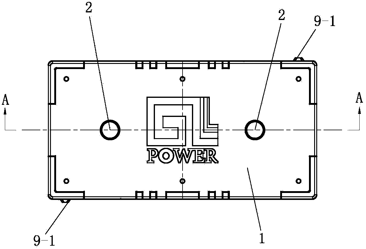
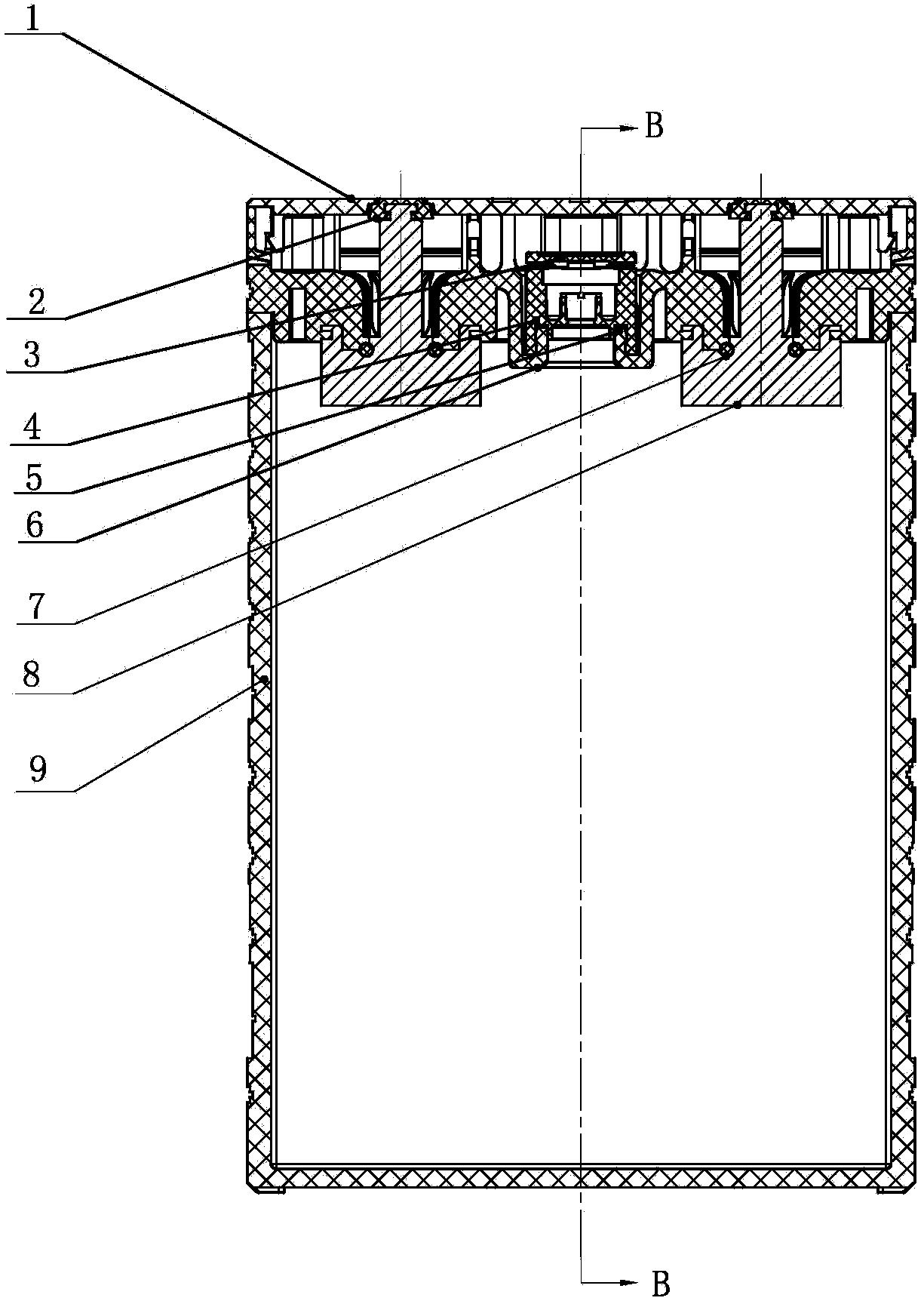
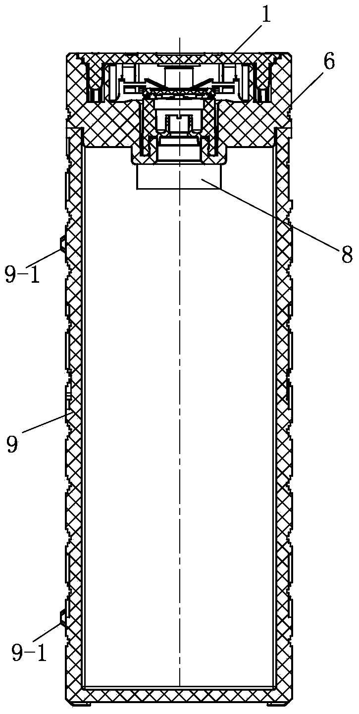
[0049] Such as Figure 1-3 As shown, the single battery of this embodiment includes a square-shaped plastic casing 9 containing battery components and having an upper opening, which is sealed with a heat sealing cover 6. A safety valve 4 is installed in the middle of the heat-sealing cover 6, and an O-ring 5 is inserted into the contact between the two. The outer end of the safety valve 4 is also covered with a decorative cover 3.

[0050] The heat sealing cover 6 is equipped with two poles 8 namely positive and negative poles. The positive and negative poles and the heat sealing cover are integrated, and the positive pole and the negative pole are symmetrically arranged on both sides of the safety valve. See Figure 19-20 , The longitudinal section of the pole 8 is in the shape of ⊥, the inner section 8-1 is cube-shaped, and the vertical sec...


PUM


Abstract

The invention discloses a battery pack. The battery pack comprises several single batteries, wherein the several single batteries are connected in series in sequence through several conductive bars connected internally; each single battery comprises a casing provided with an opening, a hot seal cover is covered at the opening part in a sealing manner, two poles are mounted on the hot seal cover, inner ends of the poles are arranged in the casing, outer ends of the poles penetrate the hot seal cover and then extend outward, and the outer ends of the poles are cylindrical; each conductive bar connected internally is manufactured by fixedly connecting a sleeve at each of the two ends of a conductive strip respectively, the sleeves are hollow cylindrical, the inside diameters of the sleeves are matched with the outside diameters of the outer ends of the poles; the outer ends of the poles are inserted into the sleeves for locking in a matched manner. According to the invention, the poles of the battery pack are connected by inserting the conductive bars quickly; the inserting connection structure is simple, the connection is firm and reliable, the contact is tight, the assembly is quick, the work efficiency can be improved, the contact resistance can be lowered, the electrical conductivity is increased, the temperature rise is lowered, the multiplying power is improved, the service life is improved, and the comprehensive performance of the battery pack is obviously improved.

Description

Technical field [0001] The invention belongs to the technical field of battery manufacturing, and specifically relates to a battery pack structure with a simple structure and easy assembly. Background technique [0002] The traditional battery includes a pole and a conductive strip, and the pole and the conductive strip are fixedly connected by screws, which have the following defects: 1. Due to multiple disassembly and assembly of the screws, the threaded sliding teeth of the pole are generated, resulting in an unstable connection between the two. 2. The conductive strip is not in close contact with the surface of the pole, and the contact resistance is large. 3. As the battery is used (vibration and thermal expansion and contraction), the screw loosens, which affects the performance and service life of the battery. To this end, Chinese Patent No. 201020504334.X discloses an assembly structure of battery poles and conductive strips, and the conductive strips and the poles are f...

Claims


Application Information

Patent Timeline
Patent Type & Authority Applications(China)
IPC IPC(8): H01M2/20H01M2/30H01M50/204H01M50/271H01M50/298H01M50/503H01M50/514H01M50/569
CPCY02E60/10
Inventor 郭治
Owner ZHEJIANG GBS ENERGY
Why Eureka
Try Eureka