Closed type composite cooling system

A compound cooling and closed technology, which is applied in the direction of cooling/ventilation/heating transformation, can solve the problems of land occupation, large amount, fluid resistance, etc., and achieve the effect of high cost, cost reduction and consumption reduction

Inactive Publication Date: 2013-12-25
GLOBAL ENERGY INTERCONNECTION RES INST CO LTD +1
View PDF5 Cites 2 Cited by
  • Summary
  • Abstract
  • Description
  • Claims
  • Application Information

AI Technical Summary

Problems solved by technology

In fact, when the power is high, a large number of air coolers are required to adopt the ambient limit temperature, which not only occupies land but also has defects such as fluid resistance and proportioning

Method used


Image

  • Closed type composite cooling system

Examples


Embodiment 1

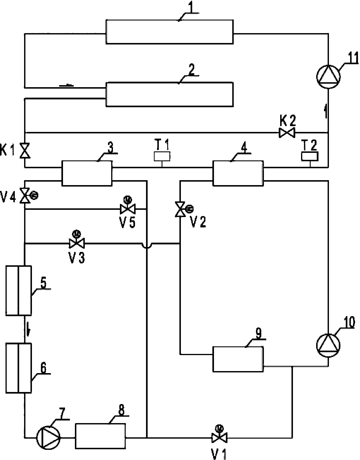
[0023] Such as figure 1 As shown, a closed composite cooling system includes a cooled device 1, an air cooler 2, a first plate heat exchanger 3, a second plate heat exchanger 4, a first chiller 5, a second chiller 6, The first cold pump (fixed frequency) 7, buffer tank 8, inclined temperature layer cold storage tank 9, the second cold pump (frequency conversion) 10, cooling water pump 11;

[0024] The cooled device 1, air cooler 2, valve K1, first plate heat exchanger 3, second plate heat exchanger 4 and cooling water pump 11 are sequentially connected to form a circulation loop, and the circulation loop is connected in parallel with a first bypass valve K2 ;

[0025] The hot side of the first plate heat exchanger 3 and the hot side of the second plate heat exchanger 4 are connected in series in a circulation loop;

[0026] The first chiller 5, the second chiller 6, the first cold pump (fixed frequency) 7, the buffer tank 8, the valve V1, the ramp type cold storage tank 9 an...


PUM


Abstract

The invention discloses a closed type composite cooling system which comprises a cooled device, an air cooler and a cooling water pump. The cooled device, the air cooler and the cooling water pump are connected to form a circulating loop through pipelines, and the system further comprises a first plate heat exchanger, a second plate heat exchanger, a water chilling unit, a cold storage tank, a buffering tank, a first cold pump and a second cold pump. The heat side of the first plate heat exchanger and the heat side of the second plate heat exchanger are connected in the circulating loop in series. The first cold pump, the water chilling unit, the cold storage tank and the buffering tank form a cold storage loop. The first cold pump, the water chilling unit, the cold side of the first plate heat exchanger and the buffering tank form a first cold releasing loop. The second cold pump, the cold storage tank and the cold side of the second plate heat exchanger form a second cold releasing loop. The design temperature of the closed type composite cooling system can be obviously lower than the ultimate temperature of the place, the structure is compact, the using number of air heat exchangers is reduced, the design capacity of the air cooler is fully utilized, cost is lowered, and the application region of the closed type circulating pure water cooling system is widened.

Description

technical field [0001] The invention relates to a closed composite cooling system. Background technique [0002] The current high-power power electronic device cooling circulating water system usually adopts the air-cooling method of a closed circulation system and a radiator for heat dissipation. Specifically, the heat brought out by the circulating water is transferred to the air cooler, and at the same time, the peripheral fan blows the heat away with the wind. However, the circulating water temperature changes with the ambient temperature. On the one hand, as the ambient temperature changes, the circulating water also changes periodically. From the point of view of the design temperature, it is basically determined by the peak temperature point that occurs locally. In fact, the temperature in various places varies greatly, and this method can only be applied to environments where the temperature difference does not change much. If in an environment with a large tempe...

Claims


Application Information

Patent Timeline
Patent Type & Authority Applications(China)
IPC IPC(8): H05K7/20
Inventor 查鲲鹏周建辉文玉良冷明全张恩龙梁柏友
Owner GLOBAL ENERGY INTERCONNECTION RES INST CO LTD
Why Eureka
Try Eureka