Combine harvester

A technology for combine harvesters and harvesting devices, which is applied to harvesters, cutters, motor vehicles, etc., can solve the problems of muddy water intrusion, and can not simply reduce manufacturing costs, so as to improve wear resistance, improve assembly workability, The effect of reducing manufacturing costs

Inactive Publication Date: 2013-12-25
YANMAR CO LTD
View PDF9 Cites 5 Cited by
  • Summary
  • Abstract
  • Description
  • Claims
  • Application Information

AI Technical Summary

Problems solved by technology

A hydraulic motor is installed on the inner peripheral side of the running track, and a hydraulic motor and a reducer are arranged on the shaft center of the driving sprocket. Therefore, it is necessary to install the driving sprocket and the reducer on the track frame with the help of the hydraulic motor casing, and there is a problem that the manufacturing cost cannot be reduced simply. Cost and other issues
In the prior art disclosed in Patent Document 2, a hydraulic motor is installed on the outer side of the running track, and a speed reduction case is provided on the track frame. Therefore, there is a problem that muddy water is easy to intrude from the bearing part of the drive sprocket.

Method used


Image

  • Combine harvester
  • Combine harvester
  • Combine harvester

Examples


Embodiment Construction

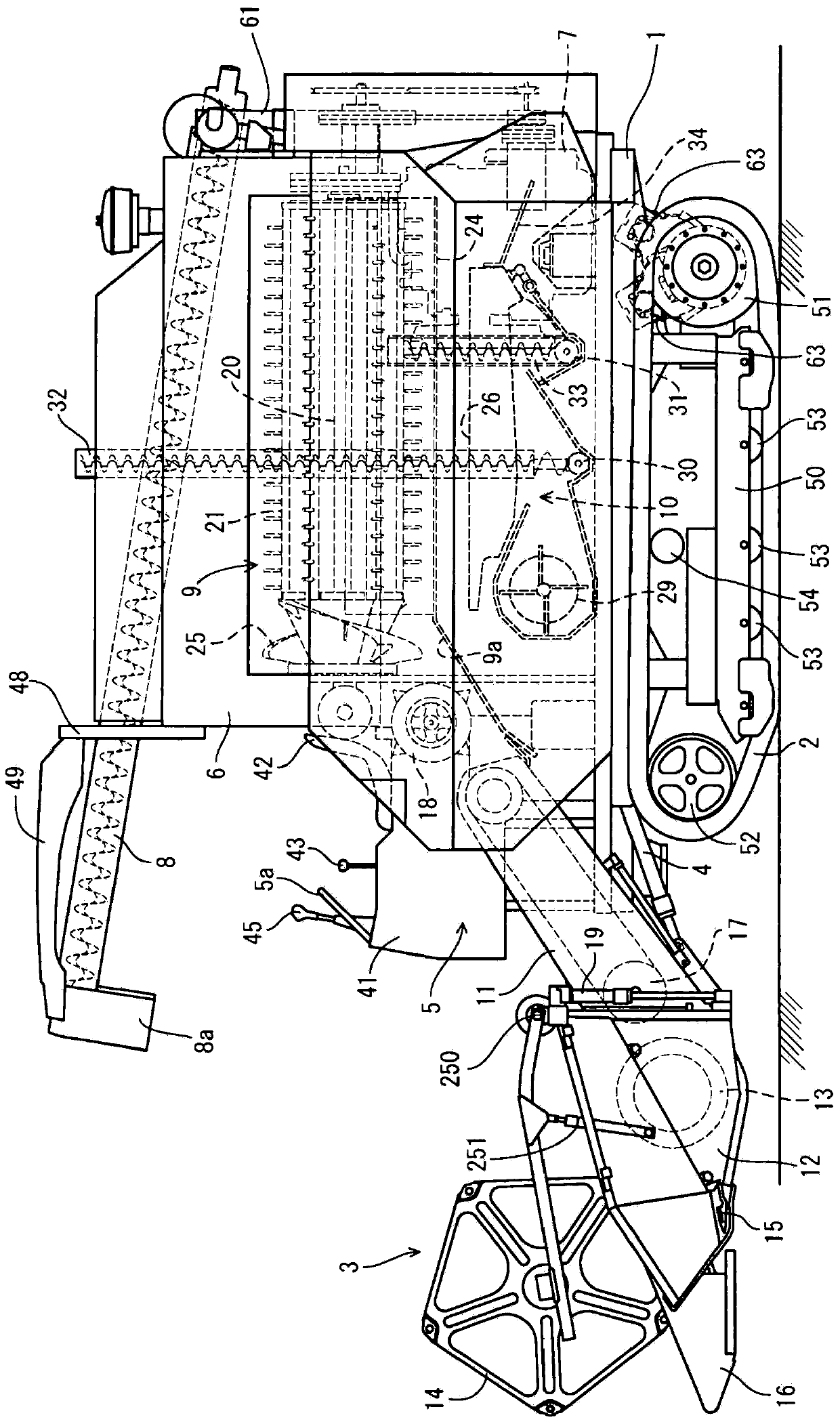
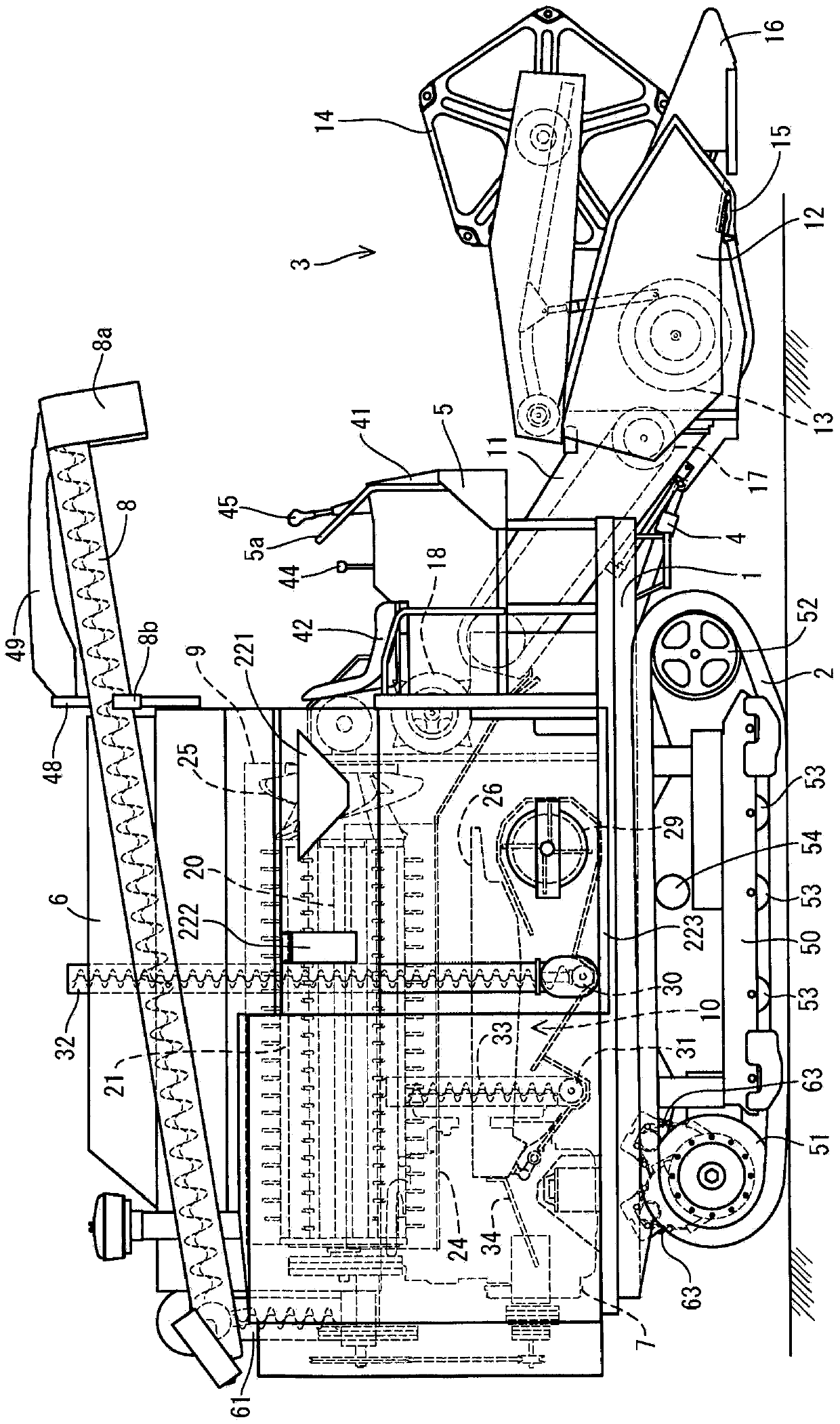
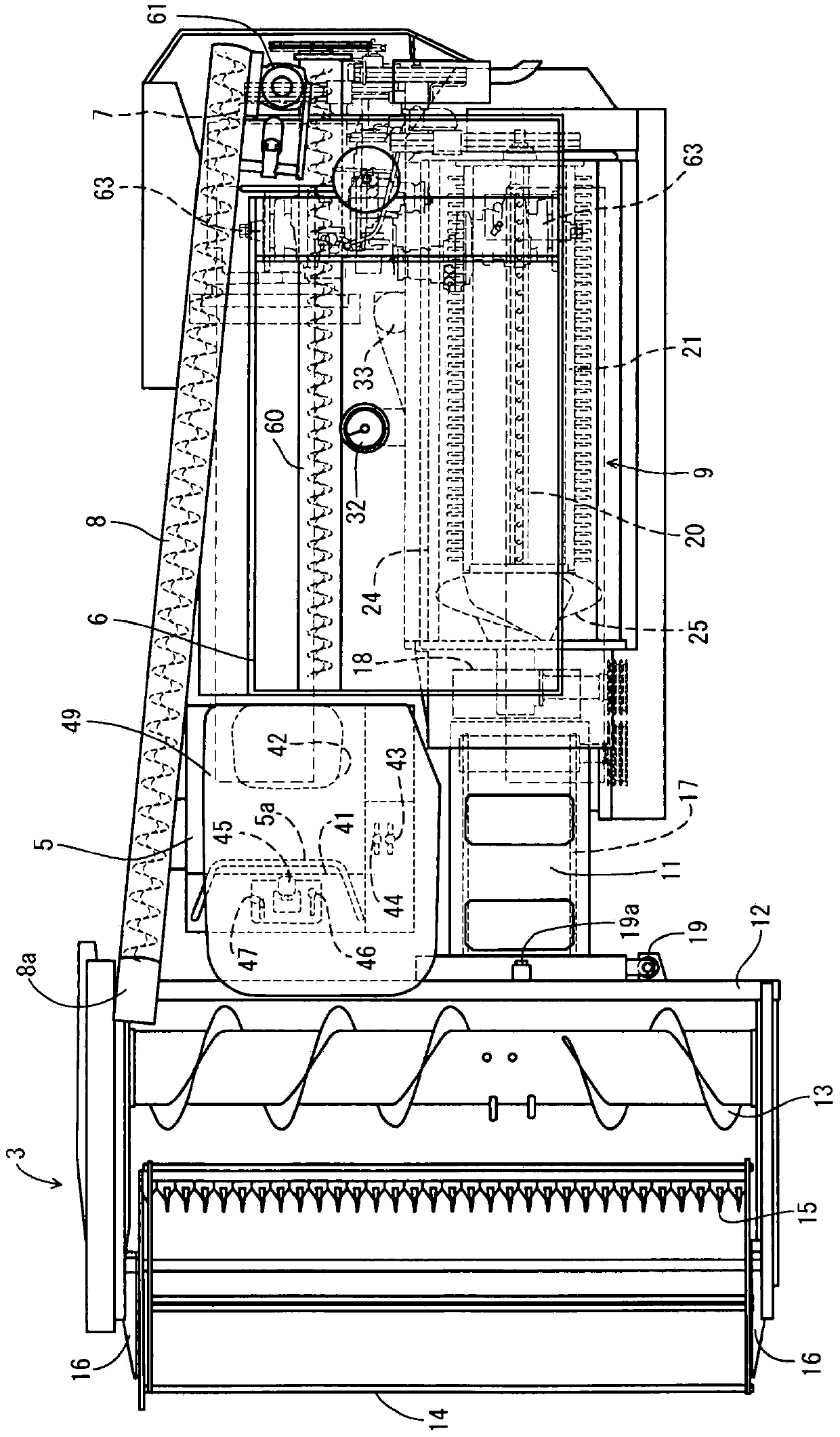
[0081] Below, based on the drawings applicable to common type combine harvesters ( Figure 1 to Figure 3 ) to illustrate specific embodiments of the present invention. figure 1 is the left side view of the combine harvester, figure 2 is its right side view, image 3 is its top view. First, refer to Figure 1 to Figure 3 , and the schematic structure of the combine harvester will be described. In addition, in the following description, the left side with respect to the advancing direction of the traveling body 1 is only called the left side, and the right side with respect to the same advancing direction is only called the right side.

[0082] Such as Figure 1 to Figure 3 As shown, the common type combine harvester of embodiment has the traveling body 1 supported via the left and right pair of crawler belts 2 made of iron as a traveling part. A harvesting device 3 for harvesting and taking in uncut rice stalks such as rice (or wheat, soybeans, or corn) is mounted on the...


PUM


Abstract

A purpose of the present invention is to provide a combine harvester, wherein mud or the like from agricultural fields can be prevented from infiltrating a spline (414) of a travel axle (300) and wear resistance of the spline (414) can be improved. Provided is a combine comprising a travel body (1) equipped with a reaping device (3), a threshing device (9), and an engine (7), a deceleration case (63) being installed in the travel body (1), a drive sprocket (51) for an endless belt (2) being axially supported on the travel axle (300) of the deceleration case (63), and the endless belt (2) mounted on the travel body (1) being driven by the engine (7) via the drive sprocket (51), wherein an axle oil seal (424) is provided between the drive sprocket (51) and an end of the travel axle (300) protruding from the deceleration case (63), and within the travel axle (300), the spline (414) axially supporting the drive sprocket (51) is lubricated.

Description

technical field [0001] The present invention relates to a combine harvester equipped with a harvesting device for harvesting uncut grain stalks in a field and a threshing device for threshing grains with cut grain stalks. Background technique [0002] Conventionally, there is a technique of continuously harvesting and threshing uncut grain stalks in a field including a traveling body having left and right crawlers and a driver's seat, a harvesting device, and a threshing device (Patent Document 1). In addition, a technique is known in which left and right crawler belts are driven by operating the left and right travel hydraulic motors with the left and right travel hydraulic pumps (see Patent Document 2). [0003] prior art literature [0004] patent documents [0005] Patent Document 1 Japanese Patent No. 4179950 [0006] Patent Document 2 Japanese Patent Application Publication No. 49-125442 Contents of the invention [0007] The problem to be solved by the invention...

Claims


Application Information

Patent Timeline
Patent Type & Authority Applications(China)
IPC IPC(8): F16H57/029A01D41/12A01D67/00B60K20/02
CPCA01D45/04A01D69/12B60K17/10B60K20/08B60Y2200/222B60Y2200/25
Inventor 清冈晃司稻冈隆也
Owner YANMAR CO LTD
Why Eureka
Try Eureka