Drag hook for mastectomy

A surgical retractor and a technique for surgery, applied in the field of retractors and their combination with retractor frames, can solve the problems of burns, affecting the surgical field, permanent scars, etc.

Inactive Publication Date: 2014-01-01
NANJING MATERNITY & CHILD HEALTH CARE HOSPITAL
View PDF7 Cites 0 Cited by
  • Summary
  • Abstract
  • Description
  • Claims
  • Application Information

AI Technical Summary

Problems solved by technology

[0002] During mastectomy, an electric knife is used to dissect the free skin flap sharply starting from the subcutaneous fat tissue. As the skin flap gradually frees up, the flap needs to be pulled up to expose the remaining tissue to continue the operation. At present, multiple assistants use hemostatic forceps Or towel forceps to pull up the skin flap, the alveolar structure of the hemostat and towel forceps will cause great damage to the skin, and will leave a large area of ​​permanent scars after the operation, and once the skin flap is

Method used


Image

  • Drag hook for mastectomy
  • Drag hook for mastectomy
  • Drag hook for mastectomy

Examples


Embodiment 1

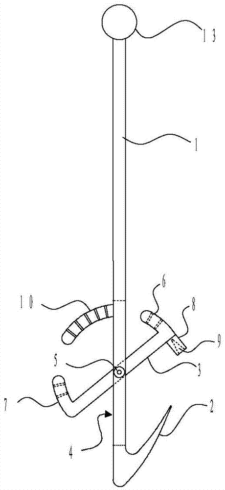
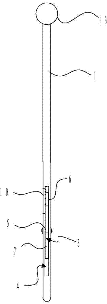
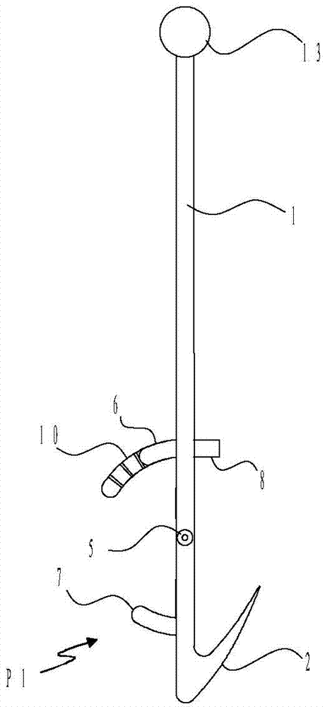
[0024] combine figure 1 , figure 2 , image 3 and Figure 4 As shown, a kind of surgical retractor of the present invention comprises a rod body 1, a hook portion 2 and a rotary rod 3, the rod body 1 has a notch 4 along the axial direction, the rotary rod 3 is installed in the notch 4 through a rotating shaft 5, and the rotary rod The two ends of 3 extend to the same side of the rotary rod 3 along the circumference to form the first tab 6 and the second tab 7, and the other side of the rotary rod 3 corresponding to the first tab 6 is provided with a protective cap 8, and the protective cap 8 is opened. There is a conical groove 9, and the position of the rod body 1 close to the upper end of the notch 4 forms a tooth seat 10 along the circumference to one side. The first tab 6, the second tab 7 and the tooth seat 10 are all arc structures with the same width. The first tongue 6 and the second tongue 7 are provided with several tooth slots, and the tooth seat is provided wit...

Embodiment 2

[0028] Please combine further Figure 5 as shown, Figure 5 It is a schematic bottom view of a retractor used for mastectomy surgery. Four surgical retractors as described in Embodiment 1 are installed, including an arc-shaped frame 12 with an arc-shaped opening 11 below the inner hollow, and a flexible connection with the arc-shaped frame 12. A plurality of surgical retractors, the upper end of the surgical retractor is provided with a spherical body 13 that can be accommodated in the arc frame 12, and the outer arc surface of the arc frame 12 is connected to the handle 14 extending obliquely upwards.

[0029] The arc mouth 11 is provided with a plurality of bayonet openings 15 which can accommodate the rod body 1 of the surgical retractor on the side close to the inner arc surface. When there are 4 surgical retractors, it is better to have 6 bayonets.


PUM


Abstract

The invention discloses a surgical drag hook, and a drag hook which consists of the surgical drag hook for mastectomy. The surgical drag hook comprises a rod body, a sharp hook part and a rotary rod, wherein the rotary rod can be withdrawn into a groove of the rod body when being positioned in a first position; and when the rotary body is positioned in a second position, the hook part is withdrawn into a groove of a protection cap. The drag hook for mastectomy comprises an arced rack and a plurality of surgical drag hooks, wherein the interior of the drag hook is hollow; an arced opening is formed in the lower part of the drag hook; the plurality of the surgical drag hooks are movably connected with the arced rack; and a sphere which can be contained and slide inside the raced rack is arranged at the upper end of each surgical drag hook. According to the surgical drag hook, a small sharp hook is used for puncturing the flap and used for lifting, thereby effectively ensuring that the flap is in the constant tension state, no wrinkles which can affect the operation are generated, the hook body can be sealed up through the protection cap, and the flap is prevented from dropping off from the hook body. When the drag hook is used, flaps on two sides of a notch are lifted from the left side and the right side by using two groups of the drag hooks respectively, and the operation can be realized by only one assistant.

Description

technical field [0001] The invention relates to the field of medical devices, in particular to a retractor for mastectomy and the combination with the retractor frame. Background technique [0002] During mastectomy, an electric knife is used to dissect the free skin flap sharply starting from the subcutaneous fat tissue. As the skin flap gradually frees up, the flap needs to be pulled up to expose the remaining tissue to continue the operation. At present, multiple assistants use hemostatic forceps Or towel forceps to pull up the skin flap, the alveolar structure of the hemostat and towel forceps will cause great damage to the skin, and will leave a large area of ​​permanent scars after the operation, and once the skin flap is loosened during the operation, it is likely to Contact with the electric knife can cause burns. And the operations of multiple assistants affect the operative field of view, which reduces the operative efficiency. [0003] Although there are some re...

Claims


Application Information

Patent Timeline
IPC IPC(8): A61B17/02
CPCA61B17/02A61B2017/00796A61B2576/02
Inventor 马晶晶杲圣倪小建
Owner NANJING MATERNITY & CHILD HEALTH CARE HOSPITAL
Why Eureka
Try Eureka