Crank machining technology

A processing technology and crank technology, which is applied in the field of crank processing technology, can solve problems such as complex crank processing technology, weak crank bearing capacity, and low processing efficiency, and achieve the effects of reasonable processing procedure arrangement, enhanced bearing capacity and strength, and improved productivity

Inactive Publication Date: 2014-01-01
QINGDAO CONNECTINROD MACHINERY
View PDF5 Cites 16 Cited by
  • Summary
  • Abstract
  • Description
  • Claims
  • Application Information

AI Technical Summary

Benefits of technology

This patented technical effect that this innovation solves by dividing it between two different processes - one involves making certain parts or tools beforehand (the first process) while another part takes place afterwards afterward. By doing these division techniques, the manufacturing time required can be reduced significantly, resulting in increased efficiency and performance over existing methods. Additionally, the final products have improved durability due to their high levels of carbon content without compromising its quality level.

Problems solved by technology

This patented technical problem addressed by this patents relates to improving the performance and durability of cams used in engines that work continuously over many hours without requiring maintenance or replacement due to their heavy weight and frequent changing directions during operation. Current manufacturing techniques have limitations such as slow productivity and lacking precision control, making them difficult to use effectively throughout the entire lifecycle of an aircraft's turbine system (which can be very expensive). Therefore there needs improvement in these technologies to make better quality cams more efficient at producing output while maintaining good machine functionality.

Method used


Image

  • Crank machining technology
  • Crank machining technology

Examples


Embodiment 1

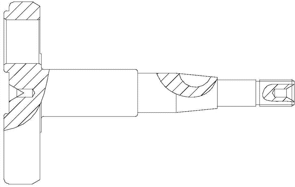
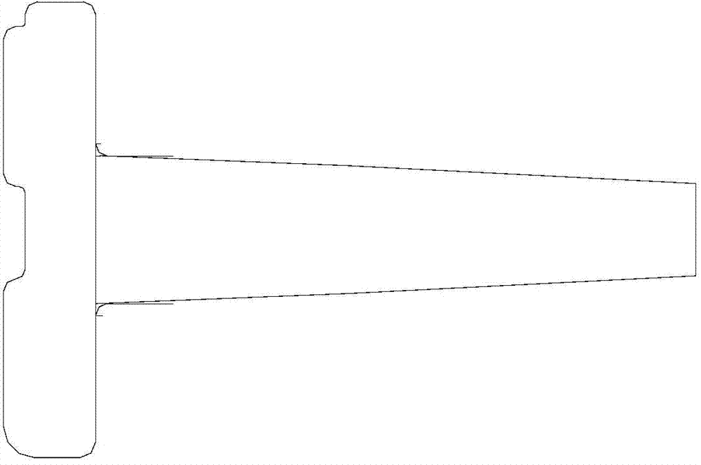
[0017] see figure 1 with figure 2 , a crank processing technology, comprising the following steps,

[0018] (1) Rough parts processing stage: Prepare the rough crank parts. The blank is made of 20Cr steel with a hardness HRC value of 20°. Place the forged crank raw parts on a flat end milling machine and process the rough parts to the specified Dimensions: Taking the surface of the rough piece as the positioning reference, use a bench drill to drill a center hole at the geometric center of the two ends of the crank;

[0019] (2) Rough machining stage: take the center holes on both ends of the crank as the positioning reference, and use a CNC lathe to carry out rough and fine turning and drilling and eccentric machining on the crank shaft and big end respectively; install semicircular keys on the milling and drilling machine The milling cutter processes the keyway on the shaft, and the thread rolling machine is used to process the shaft, and the processed workpiece is heat t...

Embodiment 2

[0022] see figure 1 with figure 2 , a crank processing technology, comprising the following steps,

[0023] (1) Rough parts processing stage: Prepare the rough crank parts. The blank parts are 20Cr steel with a hardness HRC value of 23°. Place the forged crank raw parts on a flat end milling machine and process the rough parts to the specified Dimensions: Taking the surface of the rough piece as the positioning reference, use a bench drill to drill a center hole at the geometric center of the two ends of the crank;

[0024] (2) Rough machining stage: take the center holes on both ends of the crank as the positioning reference, and use a CNC lathe to carry out rough and fine turning and drilling and eccentric machining on the crank shaft and big end respectively; install semicircular keys on the milling and drilling machine The milling cutter processes the keyway on the shaft, and the thread rolling machine is used to process the shaft, and the processed workpiece is subject...

Embodiment 3

[0027] see figure 1 with figure 2 , a crank processing technology, comprising the following steps,

[0028] (1) Rough parts processing stage: Prepare the rough crank parts. The blank is made of 20Cr steel with a hardness HRC value of 25°. Place the forged crank raw parts on a flat end milling machine and process the rough parts to the specified Dimensions: Taking the surface of the rough piece as the positioning reference, use a bench drill to drill a center hole at the geometric center of the two ends of the crank;

[0029] (2) Rough machining stage: take the center holes on both ends of the crank as the positioning reference, and use a CNC lathe to carry out rough and fine turning and drilling and eccentric machining on the crank shaft and big end respectively; install semicircular keys on the milling and drilling machine The milling cutter processes the keyway on the shaft, and the thread rolling machine is used to process the shaft, and the processed workpiece is heat-t...


PUM

PropertyMeasurementUnit
Hardnessaaaaaaaaaa
Surface hardnessaaaaaaaaaa
Hardnessaaaaaaaaaa

Abstract

The invention relates to the technical field of machining of machine parts, and particularly discloses a crank machining technology. The crank machining technology comprises the following steps: at a blank processing period, machining blanks to specified dimensions; at a coarse machining period, respectively performing coarse finish turning machining and drill carriage deviated hole machining on a crank shaft and a big head end, and performing keyway machining and thread machining on the shaft; at a fine machining period, performing fine grinding processing and machining after performing shot blasting processing on the surface of the crank. The crank machining technology has the advantages that the machining working procedures are reasonably arranged, the production and machining steps are greatly simplified, the production rate of cranks is effectively improved, the requirements on rigidity and tenacity during crank working are met at the same time, and the bearing capacity and strength of the crank are effectively improved.

Description


Claims


Application Information

Patent Timeline
Owner QINGDAO CONNECTINROD MACHINERY
Why Eureka
Try Eureka