A screen printing machine with self-alignment function of overprinting

A screen printing machine and self-alignment technology, which is applied to screen printing machines, printing machines, rotary printing machines, etc., can solve problems such as unsatisfactory, precision errors, etc., to improve production efficiency, realize full automation, and avoid errors Effect

Active Publication Date: 2016-07-27
MAXIM SMART MFG CO LTD
View PDF6 Cites 0 Cited by
  • Summary
  • Abstract
  • Description
  • Claims
  • Application Information

AI Technical Summary

Problems solved by technology

[0004] However, this technical solution has the following disadvantages: due to the movement and pressure of the scraper, the flexible screen will produce a certain amount of deformation in the length direction during each printing pass. The distance between the alignment marks is not a constant fixed value, but fluctuates up and down in a range with the screen deformation
However, there is basically no deformation of the screen frame. Therefore, when aligning through the screen frame and the alignment mark, there will always be an accuracy error due to the insurmountable printing deformation of the screen.
Therefore, it cannot meet the needs of some overprints with very high precision requirements.

Method used


Image

  • A screen printing machine with self-alignment function of overprinting
  • A screen printing machine with self-alignment function of overprinting
  • A screen printing machine with self-alignment function of overprinting

Examples


Embodiment Construction

[0019] Below in conjunction with accompanying drawing, the present invention is described in further detail, so that those skilled in the art understand:

[0020] like Figure 1-2 As shown, the labels represent:

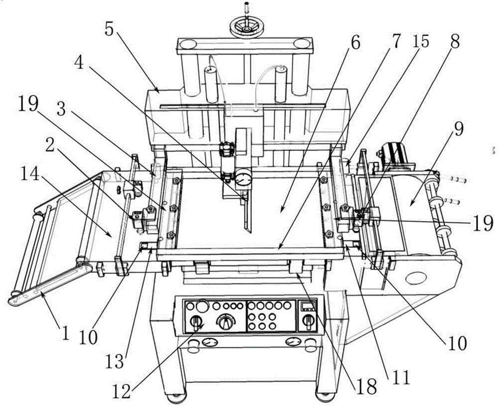
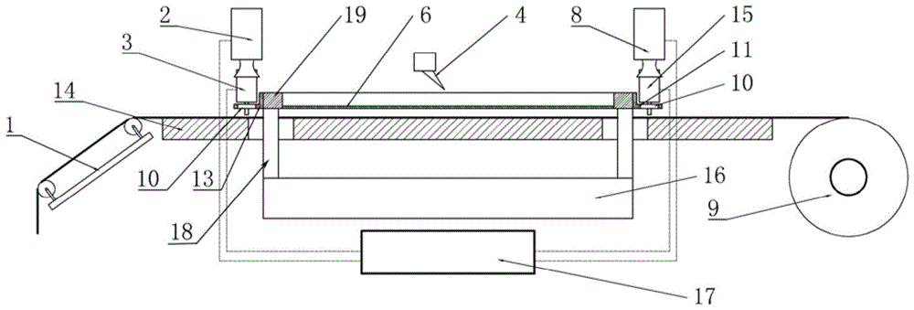
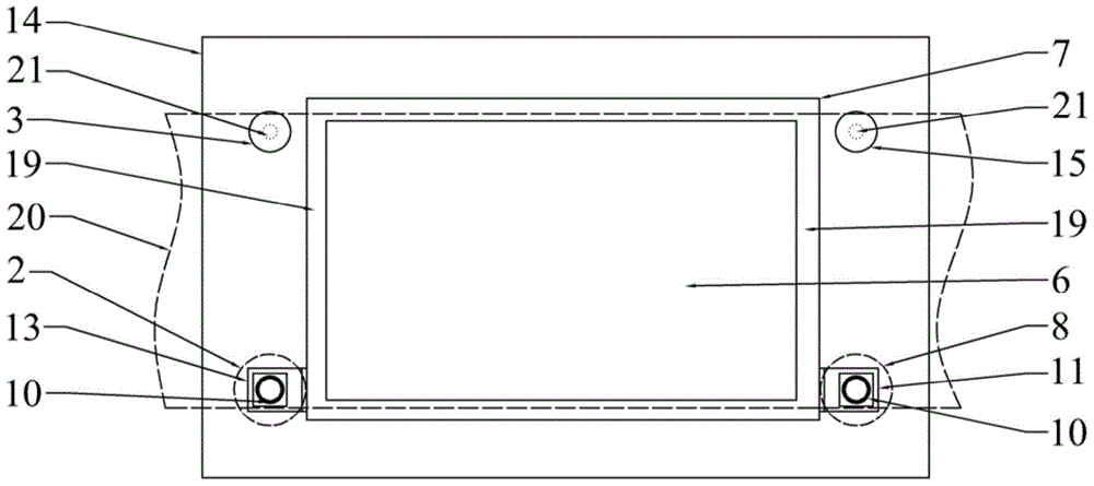
[0021] Conveyor frame 1, first CCD camera 2, first puncher 3, scraper 4, frame 5, screen plate 6, screen frame 7, second CCD camera 8, receiving roller 9, positioning hole 10, second Positioning part 11, control panel 12, first positioning part 13, printing plate 14, second puncher 15, driving mechanism 16, computer 17, column 18, longitudinal frame edge 19, web traveling area 20, punching knife 21 ,.

[0022] see Figure 1-3 As shown, a screen printing machine with overprint self-alignment function is provided in this embodiment, which includes a frame 5, and the frame 5 is fixedly provided with a computer 17 and a printing platform 14, wherein the computer 17 is arranged on the frame 5 In the inner space of the lower end ( figure 1 (not shown), the upper surfa...


PUM


Abstract

The invention relates to a screen printing machine with an overprint self-alignment function, which includes a computer and a frame, and the frame is provided with a scraper, a printing platform, a screen frame and a driving mechanism; the screen printing machine also includes a pair of punching holes A pair of positioning parts connected to the screen frame and having positioning holes respectively; a pair of punching devices are located above the printing platform and punch out two punch holes on the web at a time on the outside of the two longitudinal frames of the screen frame; The two positioning holes are respectively located outside the two longitudinal frame sides of the screen frame and above the punching position when the web is rotated in the direction of screen printing; above each positioning hole is provided with a CCD camera vertically facing the positioning hole; A hole maker and a CCD camera are connected to the computer. Its advantages are: combining the image capture technology with the driving platform, using the puncher to punch holes when the substrate is printed for the first time, and using the CCD lens to capture the punching position of the substrate in the subsequent printing to adjust the screen frame for automatic alignment . The alignment accuracy is guaranteed and the production efficiency is improved.

Description

technical field [0001] The invention relates to the technical field of screen printing machines, in particular to a screen printing machine with an overprint self-alignment function. Background technique [0002] With the development of technology, screen printing has been widely used in various industries such as LCD, IC packaging, PCB printing, packaging and decoration because of its high printing precision and good quality. The precise alignment between the screen and the substrate is an important factor that determines the printing accuracy and quality of the screen printing machine. Existing semi-automatic screen printing machines all adopt platform fixed structure and manual feeding. Every time the material is fed, the worker uses the reference line of the plate as a reference, and then roughly judges the placement position by vision to place the substrate. The defects of this printing machine are obvious, the labor intensity of the operator is high, the production e...

Claims


Application Information

Patent Timeline
Patent Type & Authority Patents(China)
IPC IPC(8): B41F15/08B41F33/00
Inventor 翟所强
Owner MAXIM SMART MFG CO LTD
Why Eureka
Try Eureka