Quick constructing method of cross-line bridge

A technology for crossing lines and bridges, which is applied in the field of rapid construction methods of cross-line bridges, can solve problems such as poor traffic, and achieve the effect of rapid bridge completion and significant social benefits.

Active Publication Date: 2014-01-01
SUZHOU RONGBAOSHENG URBAN CONSTR CO LTD
View PDF5 Cites 8 Cited by
  • Summary
  • Abstract
  • Description
  • Claims
  • Application Information

AI Technical Summary

Problems solved by technology

[0003] Highway bridges, especially full-hole bridges on urban elevated roads, are limited by design, construction, and equipment capabilities. Most of them use in-situ cast-in-place construction. Or partially closed for a long time, resulting in poor traffic

Method used


Image

  • Quick constructing method of cross-line bridge
  • Quick constructing method of cross-line bridge
  • Quick constructing method of cross-line bridge

Examples


Embodiment 1

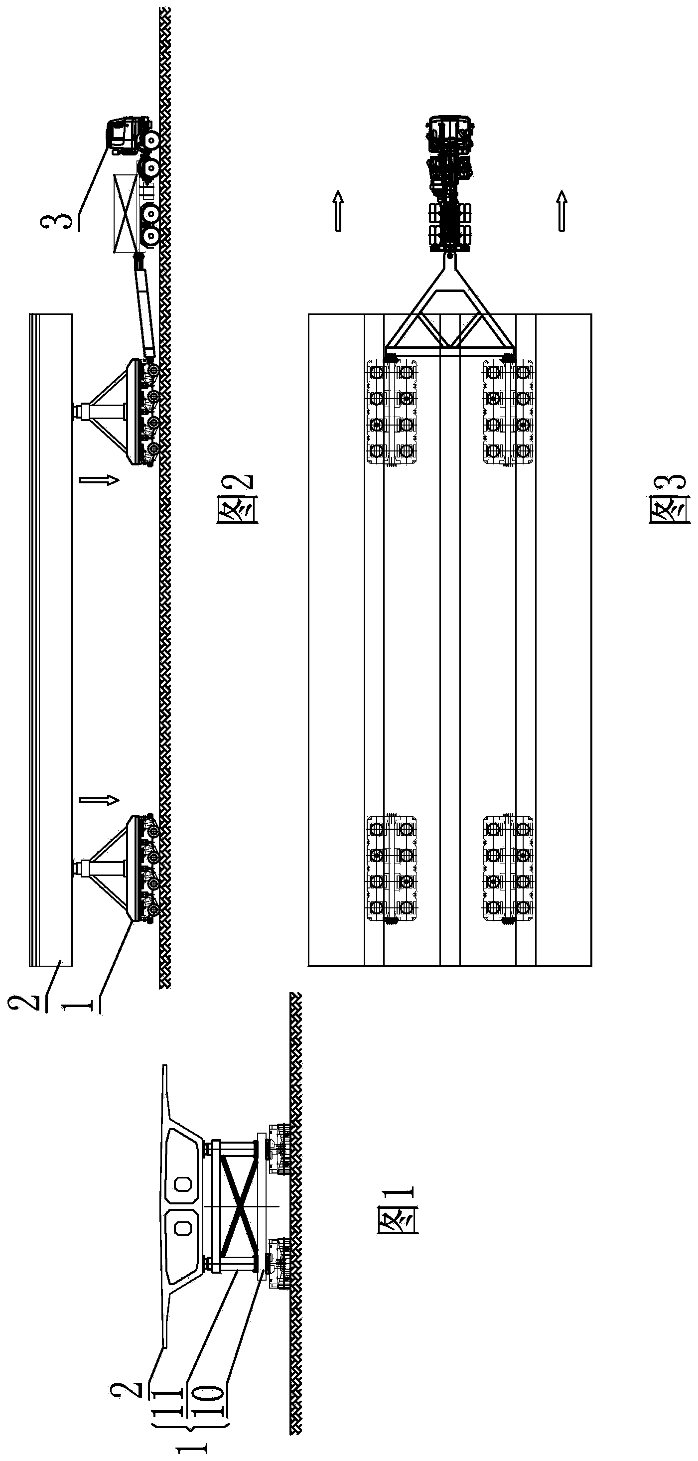
[0030] A rapid construction method for a cross-line bridge. An elevated road is erected along the construction road and disconnected at a vertical crossing position with an existing road 5 . First of all, a brief introduction to the equipment used for it - the integrated vehicle for transport and frame 1:

[0031] The frame-transporting integrated vehicle 1 includes a power platform vehicle 10 and a carrying bracket 11 arranged on the power platform. The power flatbed 10 is based on four-axis and six-axis modules, which can be spliced ​​vertically and horizontally to meet the transportation of goods of different dimensions and weights; the bottom of the power flatbed 10 is connected to a hydraulic suspension system that can rotate. The piggyback bracket 11 is used to carry the cross-line bridge segment 2. After the transportation is in place, the piggyback bracket 11 cooperates with the power flatbed truck 10 to carry out three-dimensional adjustment and positioning of the cro...

Embodiment 2

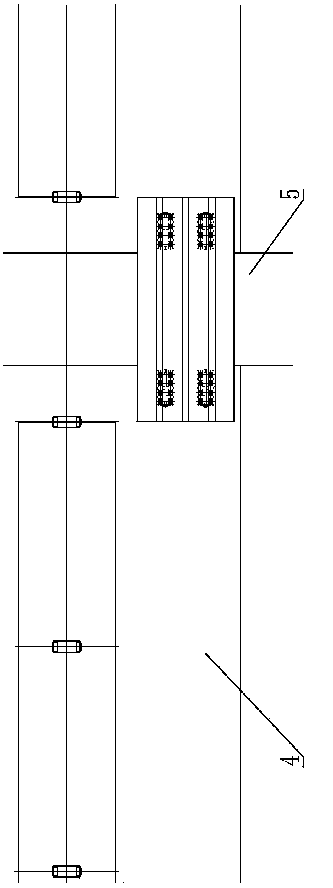
[0039] Such as Figure 10-18 Shown: The construction method specifically includes the following steps:

[0040] The prefabricated cross-line bridge segment 2 is carried by the integrated vehicle 1 to the beam yard: the integrated vehicle 1 is lowered by its own lifting system and then powered by the trailer 3 at a low position, and carried along the existing road 5 To the outside between the viaduct bridge piers at the road installation site;

[0041] The frame-transporting integrated vehicle 1 is separated from the additional trailer 3, which uses its own micro-power to rotate the vehicle 90 degrees on the spot and then uses its own suspension system to rotate 90 degrees;

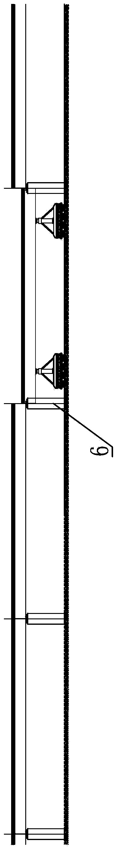
[0042] The integrated frame transport vehicle 1 is lifted by its own lifting system, so that the bottom of the span bridge segment 2 is higher than the span bridge pier support 6, and the frame transport integrated vehicle 1 enters between the viaduct bridge piers through its own micro power; The integra...


PUM


Abstract

The invention relates to a quick constructing method of a cross-line bridge. The method includes that a transportation and erection integrated trolley is adopted to move to a girder fabrication yard to carry a prefabricated cross-line bridge segment, carries the cross-line bridge segment to a specific location of a bridge installation site by adopting power of an additional trailer, is separated from the additional trailer; during carrying along a service road parallel to one side of a construction road, a suspension system rotates by 90 degrees; during carrying along an existing rod, the complete trolley rotates in place by 90 degrees, and then a rear suspension system rotates by 90 degrees; the transportation and erection integrated trolley jacks to allow the bottom of the cross-line bridge segment to be higher than cross-line bridge pier supports, and laterally moves to a position between elevated bridge cross-line piers; the transportation and erection integrated trolley descends to allow the cross-line bridge segment be supported on the cross-line bridge pier supports; the transportation and erection integrated trolley exits from the elevated bridge cross-line piers, acts repeatedly and returns to the girder fabrication yard. The method is quick in installation, and traffic of the existing road in the daytime is unaffected; quick bridge construction is realized in the true sense, impact on urban traffic is reduced to the lowest, and the method has remarkable social benefit.

Description

technical field [0001] The invention relates to the technical field of bridge construction, in particular to a rapid construction method of a cross-line bridge. Background technique [0002] The structural form of the superstructure of highway bridges or urban viaducts is generally designed as multi-span continuous beams to ensure the smoothness of driving. For each span bridge, full-hole beams can be used, and multiple T-shaped beams or small boxes can be used. Composite beams spliced ​​horizontally, or composite beams segmented longitudinally and assembled segment by segment. [0003] Highway bridges, especially full-hole bridges on urban elevated roads, are limited by design, construction, and equipment capabilities. Most of them use in-situ cast-in-place construction. Or partially closed for a long time, resulting in poor traffic. Contents of the invention [0004] The purpose of the present invention is to provide a rapid construction method for a bridge over a line...

Claims


Application Information

Patent Timeline
Patent Type & Authority Applications(China)
IPC IPC(8): E01D21/00
Inventor 李荣生李海洋
Owner SUZHOU RONGBAOSHENG URBAN CONSTR CO LTD
Why Eureka
Try Eureka