
Cross-shaped cast-in-place pile and method for constructing same

A construction method, cast-in-situ pile technology, applied in sheet pile walls, foundation structure engineering, construction, etc., to achieve the effects of saving concrete, increasing vertical bearing capacity, and small pressure-in resistance

Inactive Publication Date: 2014-01-01
ZHANGJIAGANG SHANMU NEW MATERIAL TECH DEV
View PDF0 Cites 3 Cited by
  • Summary
  • Abstract
  • Description
  • Claims
  • Application Information

AI Technical Summary

Problems solved by technology

[0004] The technical problem to be solved by the present invention is: to overcome the technical problems of foundation piles in the prior art, to provide a cross cast-in-situ pile and its construction method, which can improve the deformation resistance while improving the side resistance and end resistance

Method used


Image

  • Cross-shaped cast-in-place pile and method for constructing same
  • Cross-shaped cast-in-place pile and method for constructing same

Examples


Embodiment 1

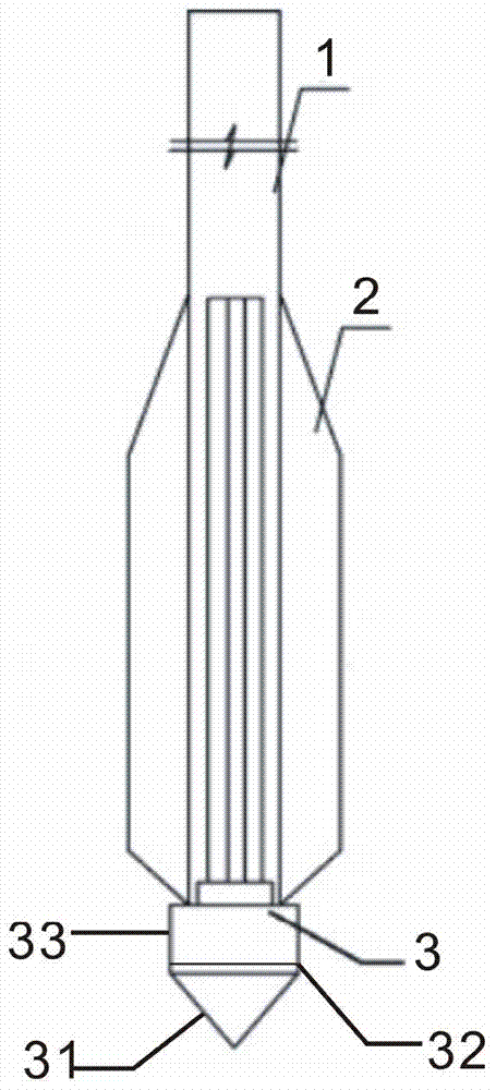
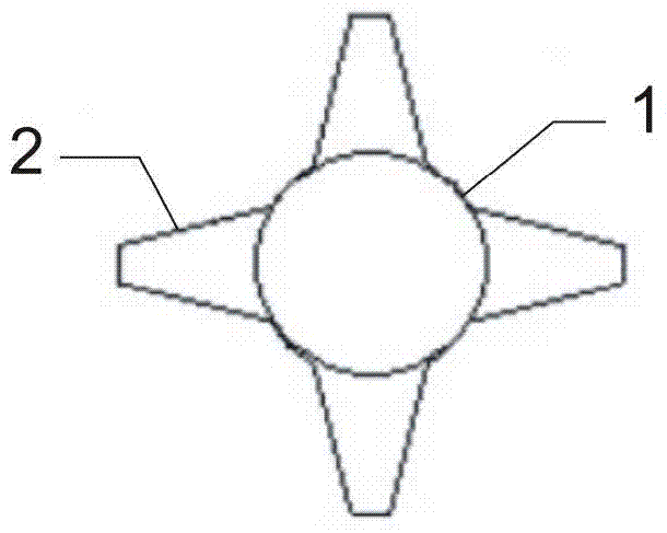
[0024] Embodiment 1: cross cast-in-situ pile, including steel pipe 1, steel flange 2, pile shoe 3, the cross section of described steel pipe 1 is circular, the middle and lower part of steel pipe 1 is welded closed steel flange 2, the steel flange 2 The cross section is cross-shaped, and the lower end of the steel flange 2 is connected to the spud can 3; the spud can 3 includes a tapered oblique cross plate 31, the bottom of the oblique cross plate 31 is fixedly connected with the end plate 33, and the diameter of the end plate 33 and The bottom diameters of the inclined cross plates 31 are the same; the length of the steel flange 2 is 0.7m.

Embodiment 2

[0025] Embodiment 2: cross cast-in-place pile, including steel pipe 1, steel flange 2, pile shoe 3, the cross section of described steel pipe 1 is circular, the middle and lower part of steel pipe 1 is welded closed steel flange 2, the steel flange 2 The cross section is cross-shaped, and the lower end of the steel flange 2 is connected to the spud can 3; the spud can 3 includes a tapered oblique cross plate 31, the bottom of the oblique cross plate 31 is fixedly connected with the end plate 33, and the diameter of the end plate 33 and The bottom diameters of the inclined cross plates 31 are the same; the length of the steel flange 2 is 0.8m.

Embodiment 3

[0026] Embodiment 3: cross cast-in-place pile, including steel pipe 1, steel flange 2, pile shoe 3, the cross section of described steel pipe 1 is circular, the middle and lower part of steel pipe 1 is welded closed steel flange 2, the steel flange 2 The cross section is cross-shaped, and the lower end of the steel flange 2 is connected to the spud can 3; the spud can 3 includes a tapered oblique cross plate 31, the bottom of the oblique cross plate 31 is fixedly connected with the end plate 33, and the diameter of the end plate 33 and The bottom diameters of the inclined cross plates 31 are the same; the length of the steel flange 2 is 0.9m.

[0027] The construction method of the above-mentioned cross cast-in-place pile has the following steps: S1. Pre-embed the concrete pile shoe; S2. After the pile driver is in place, insert the steel pipe welded with the steel convex edge into the concrete pile shoe; S3. Vibration pressure or static pressure Sink the steel pipe into the s...


PUM

PropertyMeasurementUnit
Lengthaaaaaaaaaa
Lengthaaaaaaaaaa
Lengthaaaaaaaaaa

Abstract

The invention discloses a cross-shaped cast-in-place pile which comprises a steel pipe, a steel flange and a pile shoe. The cross section of the steel pipe is circular, the middle lower portion of the steel pipe is sealed by the steel flange by means of welding, the cross section of the steel flange is cross-shaped, and the lower end of the steel flange is connected with the pile shoe. The cross-shaped cast-in-place pile has the advantages that the cross-shaped cast-in-place pile can be used for treating a foundation, and also can be used as a foundation pile; the cross-shaped cast-in-place pile is high in deformation resistance, and the vertical bearing capacity of the pile can be improved; the section of the cross-shaped cast-in-place pile is mainly circular, so that the cross-shaped cast-in-place pile can be conveniently and easily connected with pipes, and can be applied to constructing long piles and super-long piles; increase of the mold-pipe impressing resistance is low; the pile forming efficiency is high, the vertical bearing capacity can be greatly improved, and a large quantity of concrete can be correspondingly saved.

Description

technical field [0001] The invention relates to the technical field of building materials, in particular to a cross cast-in-place pile and a construction method thereof. Background technique [0002] As we all know, the vertical bearing capacity of piles is generally composed of side friction resistance and end bearing capacity. In order to improve the vertical bearing capacity of the pile, it is often necessary to maximize the potential capacity of the foundation soil and the pile itself. The special-shaped pile is the concrete embodiment of this idea. Special-shaped piles either change the cross-sectional shape of the pile body to improve the bearing capacity of the pile body; or give full play to the potential of the pile body material, change the shape of the longitudinal section of the pile body, and increase the unevenness and roughness of the pile-soil interface to achieve a higher Great side and end resistance. [0003] In recent years, my country has developed p...

Claims


Application Information

Patent Timeline
IPC IPC(8): E02D5/38E02D5/72
Inventor 杨支来徐海彬徐明哲金兆应王钦霞
Owner ZHANGJIAGANG SHANMU NEW MATERIAL TECH DEV
Features
  • Generate Ideas
  • Intellectual Property
  • Life Sciences
  • Materials
  • Tech Scout
  • Unparalleled Data Quality
  • Higher Quality Content
  • 60% Fewer Hallucinations
Learn More