Safe floor drain capable of draining water rapidly

A safe and fast technology, applied in the direction of drainage structures, waterway systems, water supply devices, etc., can solve the problems of not being able to float normally, blockage of the floor drain sewer, easy blockage of the orifice, etc. The effect of easy installation

Inactive Publication Date: 2014-01-01
戴永锋
View PDF9 Cites 6 Cited by
  • Summary
  • Abstract
  • Description
  • Claims
  • Application Information

AI Technical Summary

Problems solved by technology

The floor drain cover of this structure has the following defects: 1. The water hole is opened too small, the orifice is easy to block, the water drainage speed is slow, and the ground water is easy to overflow; 2. The water hole is opened too large, solid Debris are easy to fall into the floor drain, and it is easy to cause blockage of the floor drain or even the sewer; the large water hole will also easily make the water in the water-sealed deodorant floor drain dry and lose the deodorant function. And there is a risk of safety; 3. The shape, size and quantity of the water hole of the same floor drain cover are usually fixed, even if the size of the water hole is designed to be adjustable, as in the application number 200620165639. 6, a floor drain device, the floor drain cover will always become the bottleneck of the rapid discharge of ground water
[0005] The floor drain removes the floor drain cover or does not install it, the drainage is fast and smooth, and its bottleneck function is eliminated, but it brings new problems, such as: for the water-sealed floor drain, Not only the anti-odor function is lost, if small valuables fall into it, it will cause accidental loss, and slightly larger debris will easily fall into it and easily cause sewer blockage; In the gap of the floating cover type floor drain, it is very easy to get the cover bowl and the floating ball stuck together, making it unable to float normally, making the anti-odor function unreliable, and even unable to drain normally, and the fragile and exposed floating ball is also very easy to be damaged by cleaning tools or The collision of other objects and the deformation and damage caused by trampling on people's feet will have adverse effects on its use.
Especially, if above-mentioned floating cover type floor drain also arranges and uses the floor drain cover of existing form, can bring new problem again to the use of this floor drain, as: local area water falls vertically from the floor drain cover aperture, will directly The impact on the upper part of the floating ball weakens the floating ability of the floating ball and the bowl, and also weakens the resistance of the floating ball to debris jamming, that is, it has an adverse effect on the floating of the bowl and the floating ball; and when the floating ball floats At this time, the upper top surface of the floating ball is easy to lean against the water hole at the lower end of the floor drain cover, which makes the water inlet channel smaller and narrower, resulting in poor water intake, thereby making the drainage speed slower and the bottleneck of the floor drain cover Defects will be more prominent

Method used


Image

  • Safe floor drain capable of draining water rapidly
  • Safe floor drain capable of draining water rapidly
  • Safe floor drain capable of draining water rapidly

Examples


Embodiment 1

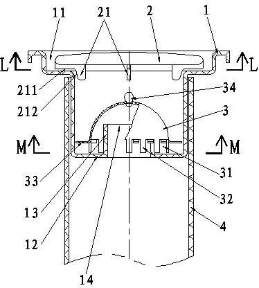
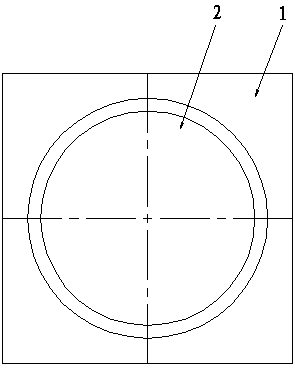
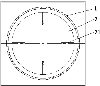
[0027] The floor drain of embodiment 1 of the present invention (structure sees figure 1 — Figure 4 ), including a floor drain seat 1 and a floor drain cover 2 located at its upper end, its structural feature is that: at least three evenly distributed "7"-shaped ribs 21 are provided on the lower side of the floor drain cover 2. The ribs 21 are supported on the bottom surface of the floor drain seat groove, so that the surrounding space where the convex rib 21 of the floor drain cover 2 contacts with the seat groove 11 forms a preset water inlet gap, so that the ground water can flow through the water inlet gap and Pour into the floor drain. The floor drain cover 2 of the present invention is preferably a non-orifice floor drain cover.

[0028] The upper end of the above-mentioned floor drain seat 1 is provided with a seat groove 11, so that the above-mentioned floor drain cover 2 is placed in the seat groove 11, and a predetermined water entry gap is provided between the f...

Embodiment 2

[0038] The floor drain of embodiment 2 of the present invention (structure sees Figure 5-Figure 9 ), including a floor drain seat 1 and a floor drain cover 2 located at its upper end, and its structural feature is that: at least three evenly distributed "7"-shaped ribs 21 are provided on the lower side of the floor drain cover 2. The ribs 21 are supported on the bottom surface of the floor drain seat, so that a predetermined water entry gap is provided between the floor drain cover 2 and the bottom surface of the floor drain seat 1, so that ground water can flow through the gap and be poured into the floor drain.

[0039] The upper end of the floor drain seat 1 is provided with a seat groove 11, so that the above-mentioned floor drain cover 2 is placed in the seat groove 11, and a predetermined water entry gap is provided between the floor drain cover 2 and the side wall of the seat groove 11 of the floor drain seat 1 The lower end of the floor drain seat 1 is also provided w...


PUM


Abstract

The invention discloses a safe floor drain capable of draining water rapidly. The safe floor drain comprises a floor drain seat and a floor drain cover positioned at the upper end part of the floor drain seat, wherein a seat groove is formed in the upper end part of the floor drain seat; the floor drain cover is placed in the seat groove; preset water inlet gaps are formed between the floor drain cover and each side wall of the seat groove; a preset water inlet gap is formed between the floor drain cover and the bottom surface of the seat groove; a seat hole and a separated water seal groove are formed in the lower end of the floor drain seat, wherein the water seal groove is movably sleeved in the pipe end of a floor drain pipe; a hole shoulder and a drain hole are formed in the seat bottom of the water seal groove; the port of the drain hole is covered with a cup with a gap and vertical teeth; transverse teeth are formed in the lower part of the cup; a preset water outlet gap is formed between the cup and the drain hole as well as the hole shoulder; accumulated water forms a water seal structure in the water sea groove; a siphon is arranged in the drain hole in a sleeved manner; the safe floor drain is characterized by further comprising a water surrounding plate and a steam surrounding hole. The safe floor drain provided by the invention has the advantages that the inflow of the accumulated water is faster, the drainage is smoother, the odor-resistant effect is more durable, the problem brought by possible leakage around the floor drain pipe is solved, and the use is more convenient.

Description

[0001] This case is a divisional application with an application date of October 13, 2009, an application number of 200910112627.5, and an invention name of a fast drainage safety floor drain. technical field [0002] The invention relates to a floor drain, which belongs to a floor drain especially suitable for indoor use. Background technique [0003] In the existing floor drain with a cover, the accumulated water on the ground must flow from the end face of the floor drain cover and then fall into the floor drain from the water hole on the floor drain cover or be discharged into the sewer (although the accumulated water can be drained from the floor drain cover and the floor drain seat) leaked through the gap, but only a negligible small part, the gap is not used as a drainage channel, and is easily blocked by fine dirt and sludge in the stagnant water). The floor drain cover of this structure has the following defects: 1. The water hole is opened too small, the orifice is...

Claims


Application Information

Patent Timeline
Patent Type & Authority Applications(China)
IPC IPC(8): E03C1/28E03F5/04
Inventor 戴永锋
Owner 戴永锋
Why Eureka
Try Eureka