
Tunnel supporting structure across active fault

A technology of active faults and supporting structures, applied in tunnels, tunnel linings, shaft linings, etc., can solve the impact of construction safety on lining strength and stability, can not fully exert the self-supporting capacity of surrounding rock, and affect lining strength and stability etc. to achieve good tensile-extrusion damage resistance, good resistance to fault creep and dislocation damage, and good shear damage resistance.

Active Publication Date: 2014-01-01
SICHUAN DEPT OF TRANSPORTATION HIGHWAY PLANNING PROSPECTING & DESIGN RES INST
View PDF1 Cites 30 Cited by
  • Summary
  • Abstract
  • Description
  • Claims
  • Application Information

AI Technical Summary

Problems solved by technology

In the above-mentioned invention patent, a foam concrete layer is set between the primary support and the secondary lining. After the completion of the primary support and before the construction of the secondary lining, the construction of the foam concrete layer is required, so it cannot be installed in the primary support. If the secondary lining is applied in time after the protection is stable, the self-supporting capacity of the surrounding rock cannot be fully utilized, which will affect the safety of construction, the strength and stability of the lining
At the same time, if a waterproof layer is set between the secondary lining and the foam concrete layer, it will further hinder the construction of the secondary lining; if no waterproof layer is set between the secondary lining and the foam concrete layer, due to the poor water permeability of the foam concrete Well, it will cause the loss of moisture in the concrete when the secondary lining is poured, resulting in plastic shrinkage cracks or pockmarks in the secondary lining, which will affect the strength and stability of the lining

Method used


Image

  • Tunnel supporting structure across active fault
  • Tunnel supporting structure across active fault

Examples


Embodiment Construction

[0017] The present invention will be further described below in conjunction with the accompanying drawings and embodiments.

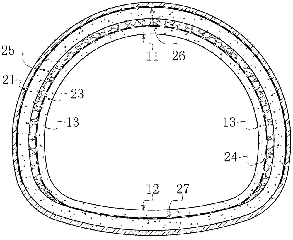
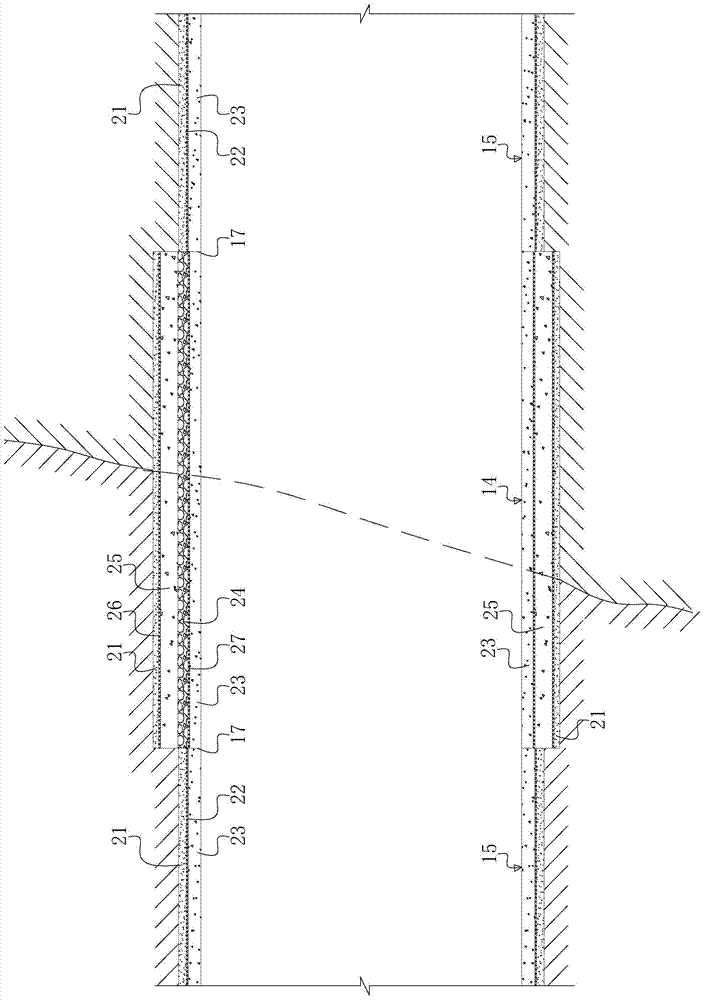
[0018] Such as figure 1 , figure 2 As shown, the tunnel support structure spanning active faults of the present invention includes a vault 11, an inverted arch 12, and two side walls 13 along the tunnel ring direction, and includes a fault spanning section 14 and a fault spanning section 14 axially along the tunnel longitudinal direction. The ordinary support section 15 connected to both ends; the ordinary support section 15 adopts a composite lining structure, including the primary support 21 on the radial outside, the secondary lining 23 on the radial inside, and the primary support 21 and The waterproof layer 22 between the secondary lining 23; along the radial direction of the tunnel, the fault spanning section 14 is respectively provided with a secondary lining 23, a foam concrete layer 24, and an initial support 21 from the inside to the outside...


PUM


Abstract

The invention relates to a tunnel supporting structure, and in particular to a tunnel supporting structure across an active fault. The tunnel supporting structure comprises a fault across section and common supporting sections connected with the two ends of the tunnel supporting structure, wherein the common supporting sections adopt combined lining structures; the fault across section is orderly provided with a secondary lining, a foam concrete layer, a primary lining, a first waterproof layer and a preliminary support from inside to outside along the radial direction of the tunnel; the primary support, the first waterproof layer and the primary lining form the combined lining structure. The tunnel supporting structure is capable of overcoming the problem of application time selection, and is safe and convenient to construct. The primary lining is capable of partially bearing stress generated by the fault due to creep; in the meantime, the foam concrete is capable of providing a displacement space and absorbing energy; finally, the secondary lining is used for forming safety stock of the structure and ensuring that the clearance is not affected by fault movement; the tunnel supporting structure is high in safety storage, and has excellent shock resistance and excellent ability of resisting damage caused by fault creep and fault movement.

Description

technical field [0001] The invention relates to a tunnel support structure, in particular to a tunnel support structure spanning active faults. Background technique [0002] A tunnel is an engineering structure built underground and is widely used in fields such as transportation, mining, water conservancy, and national defense. The current tunnel is usually constructed using the new Austrian method, and the support structure is a composite lining structure, including the vault, invert and side walls on both sides along the tunnel ring direction, including the outer primary support and the inner secondary support along the tunnel radial direction. Secondary lining and waterproofing layer between primary support and secondary lining. [0003] With the rapid development of my country's transportation industry, the area where tunnels are built is becoming wider and wider. According to the existing technical specifications, in the tunnel engineering, if a fault is encountered,...

Claims


Application Information

Patent Timeline
IPC IPC(8): E21D11/00E21D11/38
Inventor 王联林国进李玉文郑金龙郑建国田尚志李晓洪高世军朱长安向龙
Owner SICHUAN DEPT OF TRANSPORTATION HIGHWAY PLANNING PROSPECTING & DESIGN RES INST
Learn More