
Front end PTO structure on a diesel engine

A diesel engine and power output technology, which is applied in the field of front-end power output structure and front-end full power output structure, can solve the problems of increasing power output requirements, inability to meet high power output, and affecting the working life of the belt, and achieve output High power, easy to disassemble, and reduce design and production costs

Active Publication Date: 2015-10-28
JIANGSU SIDA POWER MECHANICAL GROUP
View PDF5 Cites 0 Cited by
  • Summary
  • Abstract
  • Description
  • Claims
  • Application Information

AI Technical Summary

Problems solved by technology

The advantage of this direct-connected power output structure is that the structure is simple, the parts are easy to process, the manufacturing cost is low, and it can complete a certain power output, but its front-end shortcomings are gradually exposed with the development of the vehicle, specifically: (1) With the large-scale development of the whole vehicle, the power output requirements of the engine are increasing, and its front-end structure is pre-tightened by the starting bolt, so that the maximum static friction force generated between the crankshaft pulley and the crankshaft cannot meet the high-power requirements. Output requirements; (2) With the prolongation of working hours, the front crankshaft pulley has a high temperature phenomenon, which causes the power transmission belt to overheat, and individual "burning belt" phenomena appear, thus affecting the working life of the belt

Method used


Image

  • Front end PTO structure on a diesel engine
  • Front end PTO structure on a diesel engine
  • Front end PTO structure on a diesel engine

Examples


Embodiment Construction

[0025] The present invention will be further described below in conjunction with specific drawings.

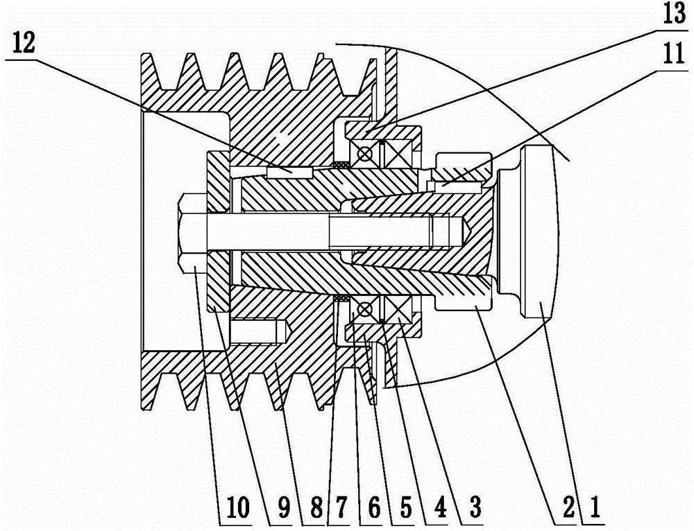
[0026] Such as Figure 3 ~ Figure 6 As shown: the front end power output structure on the diesel engine includes crankshaft 1, crankshaft timing gear 2, tapered shaft 2-1, ring gear 2-2, front end oil seal 3, spacer ring 4, gear chamber cover 5, front end Bearing 6, rubber sleeve 7, crankshaft pulley 8, start bolt pressure plate 9, start bolt 10, first flat key 11, second flat key 12, extension 13, cooling hole 14, through hole 15, etc.

[0027] Such as image 3 As shown, the present invention comprises the crankshaft 1 that is fixed on the diesel engine block, and the crankshaft timing gear 2 is set by the first flat key 11 at the front end of the crankshaft 1; Figure 5 As shown, the crankshaft timing gear 2 includes a tapered shaft 2-1, one end of the tapered shaft 2-1 is a large end, and the other end is a small end, and the small end of the tapered shaft 2-1 extends out...


PUM


Abstract

The invention relates to a front-end power output structure of a diesel engine. The front-end power output structure comprises a crankshaft fixed on a diesel engine body, and the front end of the crankshaft is sleeved with a crankshaft timing gear. The front-end power output structure is characterized in that the crankshaft timing gear comprises an arc-shaped shaft, one end of the arc-shaped shaft is a large end, the other end of the arc-shaped shaft is a small end, the small end of the arc-shaped shaft extends out of a gear chamber cover, a gear ring is arranged at the large end of the arc-shaped shaft, and the small end of the arc-shaped shaft is sleeved with a crankshaft pulley. An extending-out part is formed by extending outwards in the axial direction of the arc-shaped shaft at the position of the gear chamber cover where the arc-shaped shaft extends out, and a front-end oil seal, a space ring and a front-end bearing are sequentially arranged in a cavity between the extending-out part and the arc-shaped shaft. A concave cavity is formed on the rear end face of the crankshaft pulley, and the extending-out part of the gear chamber cover extends into the concave cavity on the rear end face of the crankshaft pulley. The front-end power output structure is reasonable in structure, flexible to produce, high in output power and load bearing capability and convenient to dismantle.

Description

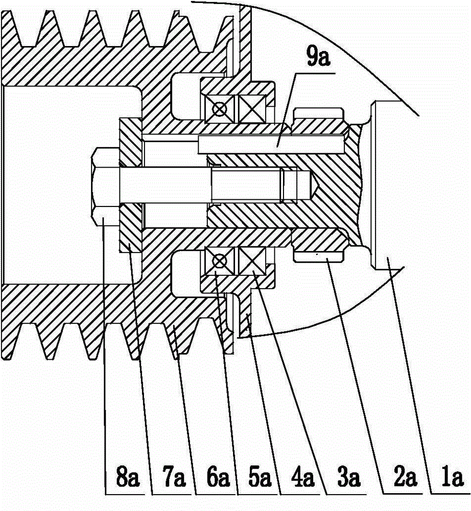
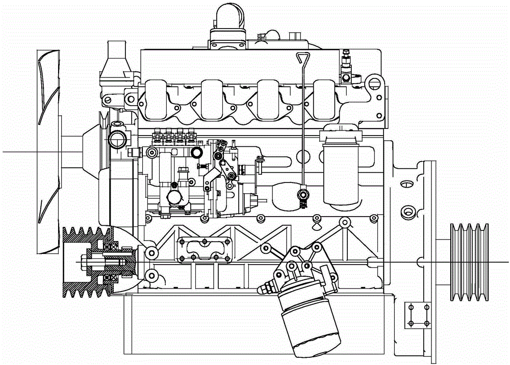
technical field [0001] The invention relates to a front-end full-power output structure, in particular to a front-end power output structure on a diesel engine, and belongs to the technical field of mechanical structures. Background technique [0002] For the previous engine power output structure, it mainly relies on the output of the flywheel end of the engine, and the front end can only complete a small part of the power output. The front-end structure of its power output is as follows: figure 1 , figure 2 As shown, 1a is the crankshaft, 2a is the gear, 3a is the oil seal, 4a is the gear chamber cover, 5a is the bearing, 6a is the crankshaft pulley, 7a is the bolt pressure plate, 8a is the starting bolt, 9a is the flat key. The advantage of this direct-connected power output structure is that the structure is simple, the parts are easy to process, the manufacturing cost is low, and it can complete a certain power output, but its front-end shortcomings are gradually exp...

Claims


Application Information

Patent Timeline
Patent Type & Authority Patents(China)
IPC IPC(8): F02B61/06
Inventor 尤涛史秉丰王磊刘群
Owner JIANGSU SIDA POWER MECHANICAL GROUP
Learn More