
Ballistic parameter-recording device
A ballistic parameter and recording device technology, applied in the direction of ammunition, ammunition test, weapon accessories, etc., can solve the problems of incapable projectile and relative speed test of rigid tail.
- Summary
- Abstract
- Description
- Claims
- Application Information
AI Technical Summary
Problems solved by technology
Method used
Image

Examples
Embodiment Construction
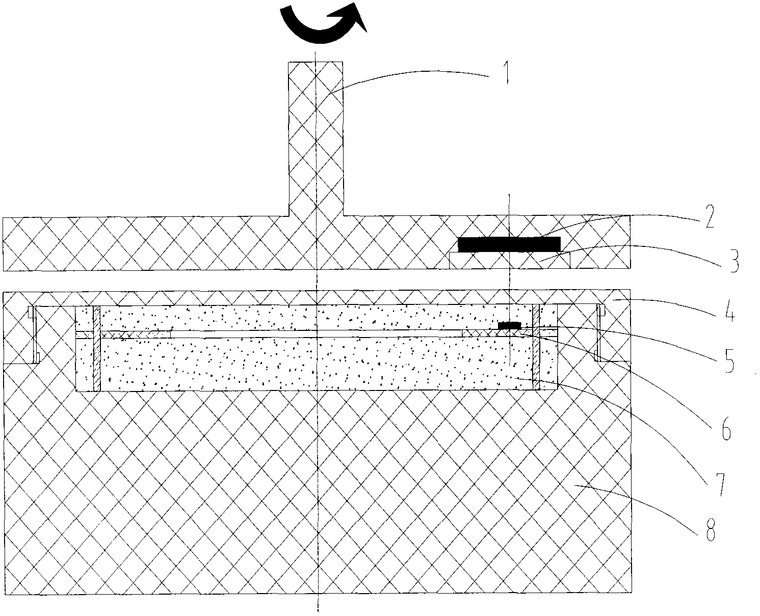
[0016] The magnet base 1 is in the shape of a disc, with a vertically upward cylindrical protrusion at the center of the upper part. The bottom of the magnet base 1 near the edge has a circular step-shaped groove, and the magnet 2 is installed in the bottom groove. The magnet sealing cover 3 The magnet 2 is fixed by threaded connection with the circular groove of the magnet base 1 , and the outer surface of the magnet sealing cover 3 is flush with the bottom surface of the magnet base 1 .
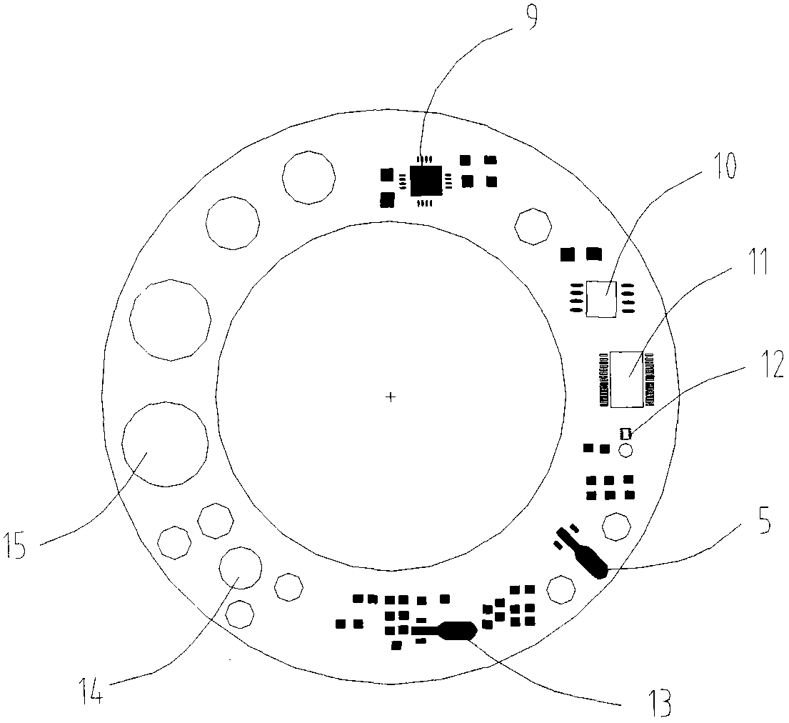
[0017] The recorder circuit board 6 is in the shape of an annular sheet, along which an accelerometer 9, a memory 10, a processor 11, an antistatic chip 12, a power chip 13, a recoil switch 14, and a battery 15 are arranged, and the detector 5 is welded on On the recorder circuit board 6.
[0018] The recorder base 8 is cylindrical, and the upper center part has a cylindrical groove with an upward opening. The recorder circuit board 6 is placed in the groove, and its outer diameter is close...
PUM
 Abstract
Description
Claims
Application Information