Helix traveling wave tube dynamic phase velocity gradually-changed thread pitch distribution structure and design method

A technology of gradual pitch and design method, which is applied to the circuit components of transit time type electron tubes, etc., can solve the problem of the increase of high-order harmonic components of the output signal, and achieve the purpose of suppressing high-order harmonic components, improving performance, and improving electronic components. The effect of efficiency

Inactive Publication Date: 2014-01-01
UNIV OF ELECTRONIC SCI & TECH OF CHINA
View PDF4 Cites 12 Cited by
  • Summary
  • Abstract
  • Description
  • Claims
  • Application Information

AI Technical Summary

Problems solved by technology

However, the use of a dynamic phase velocity gradient structure will lead to an increase in the

Method used


Image

  • Helix traveling wave tube dynamic phase velocity gradually-changed thread pitch distribution structure and design method
  • Helix traveling wave tube dynamic phase velocity gradually-changed thread pitch distribution structure and design method
  • Helix traveling wave tube dynamic phase velocity gradually-changed thread pitch distribution structure and design method

Examples


Embodiment Construction

[0031] The technical solutions of the present invention will be further described in detail below in conjunction with the accompanying drawings and specific embodiments.

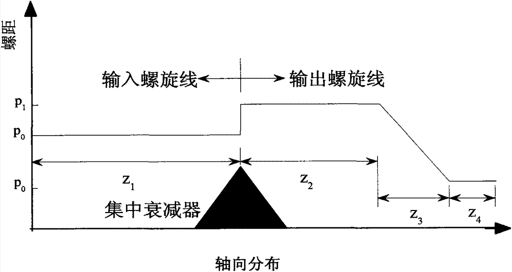
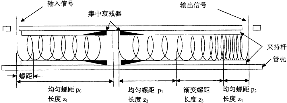
[0032] refer to Figure 1-Figure 2 , a dynamic phase velocity gradient pitch distribution structure of a helical traveling wave tube. The whole helix is ​​divided into an input helix and an output helix, separated by a cut (the two sides of the cut are concentrated attenuators to suppress electromagnetic wave reflection, wherein the input helix The length of the line is z1 and the pitch is p0; the output helix is ​​divided into three sections: the first uniform helical segment, the gradual helical line segment, and the second uniform helical segment. The length of the first uniform pitch segment is z2 and the pitch is p1; the gradual helical pitch segment Length is z3, and its pitch value changes gradually to p2 from p1 evenly; The length of the second section uniform helical section is z4 pitch and is p2.Fu...


PUM


Abstract

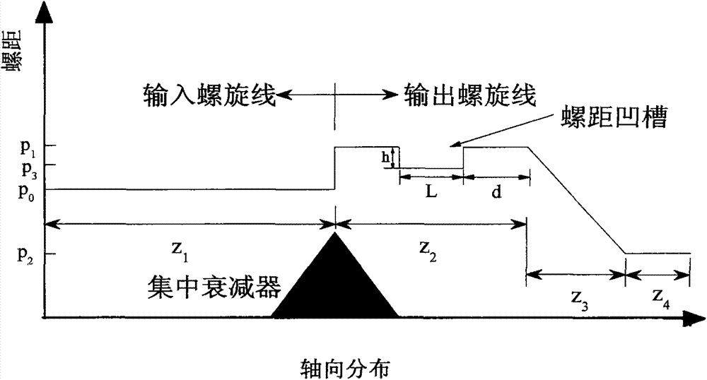
The invention discloses a helix traveling wave tube dynamic phase velocity gradually-changed thread pitch distribution structure and a design method. A helix is divided into an input helix body and an output helix body, the input helix body is separated from the output helix body through a cutting-off device, and concentrated attenuators are arranged on the two sides of the cutting-off device and used for restraining reflection of electromagnetic waves. The output helix body is divided into three sections, a thread pitch groove is additionally formed in front of the gradually-changed thread pitch section z3 of the output helix body, the thread pitch groove is mainly determined through three structure parameters including the groove depth h, the groove width L and the distance d between the groove and the gradually-changed thread pitch section z3, and the dynamic phase velocity gradually-changed thread pitch distribution structure with the groove is formed. According to the helix traveling wave tube dynamic phase velocity gradually-changed thread pitch distribution structure and the design method, the electronic efficiency of a helix traveling wave tube is improved through the dynamic phase velocity gradually-changed structure, and meanwhile the aim of restraining high harmonic components of output signals is achieved through the groove.

Description

technical field [0001] The invention belongs to the technical field of helical traveling wave tubes, and relates to a dynamic phase velocity gradient pitch distribution structure and a design method of a helical traveling wave tube, in particular to a helical traveling wave tube with a grooved dynamic phase velocity gradient Pitch distribution structure and design method. Background technique [0002] In satellite communication, data transmission and other space applications, helical traveling wave tubes are usually used to amplify radio frequency signals. The helical traveling wave tube interacts with the electron beam through the electromagnetic field formed by the input radio frequency signal, and converts the kinetic energy of the electron beam into electromagnetic energy, thereby realizing the amplification of the radio frequency signal. Compared with traveling wave tubes with other high-frequency structures, helical traveling wave tubes have the characteristics of wid...

Claims


Application Information

Patent Timeline
IPC IPC(8): H01J23/27H01J23/30
Inventor 胡玉禄李斌李建清朱小芳杨中海郭佶玙
Owner UNIV OF ELECTRONIC SCI & TECH OF CHINA
Why Eureka
Try Eureka