
Crimp terminal

一种压接端子、压接部的技术,应用在连接、导电连接、连接绝缘等方向,能够解决耐久性降低、联接部不能具有刚性、联接部损坏等问题

Inactive Publication Date: 2014-01-01
SUMITOMO WIRING SYST LTD
View PDF4 Cites 4 Cited by
  • Summary
  • Abstract
  • Description
  • Claims
  • Application Information

AI Technical Summary

Problems solved by technology

Therefore, the coupling portion cannot have sufficient rigidity, causing problems such as reduced durability and damage to the coupling portion

Method used


Image

  • Crimp terminal
  • Crimp terminal
  • Crimp terminal

Examples


Embodiment Construction

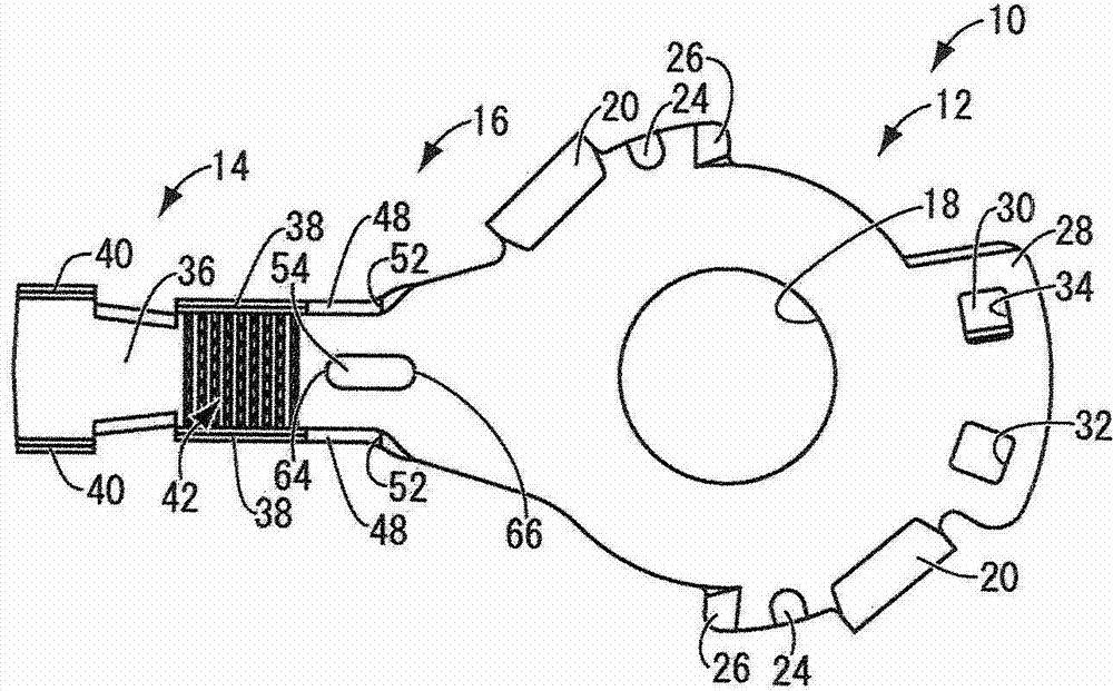
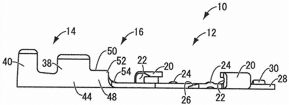
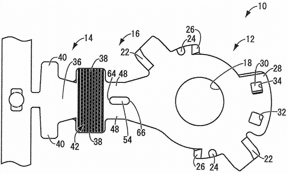
[0023] The crimp terminal according to the present invention consists of Figure 1 to Figure 5 Mark 10 in the mark. The crimp terminal 10 is integrally formed to include a connection portion 12 which is conductively connected to a connection object, a crimp portion 14 which has a function of being bonded by crimping onto a core wire 58 of a covered wire 56 The fixed core wire crimping portion 38, the coupling portion 16 extends between the connecting portion and the crimping portion.

[0024] The crimp terminal 10 is formed of, for example, a conductive metal capable of withstanding processes such as extrusion and punching, such as brass, copper, copper alloys, aluminum, and aluminum alloys. The crimp terminal 10 has a substantially uniform thickness as a whole.

[0025] The connection portion 12 has a substantially elliptical flat plate shape, and the through hole 18 passes through the center portion. The through hole 18 can accommodate a terminal bolt screwed into a prede...


PUM


Abstract

A crimp terminal (10) has a connecting portion (12) that is conductively connected to an electrical connection target, a crimp portion (14) that is fixed by crimping to a core (58) of a coated wire (56), and a link (16) extending between the connecting portion (12) and the crimp portion (14). The crimp portion (14) has a placement portion (36) on which the core (58) of the coated wire (56) is placed, and a core crimping portion (38) protruding from opposite edges of the placement portion (36). Extended portions (48) are provided on ends of the core crimping portions (38) toward the link (16) and at least one engaging corner (52) is formed on an upper end surface (50) of each of the extended portions (48).

Description

technical field [0001] The present invention relates to a crimp terminal which is connected by crimping to an exposed core wire at an end portion of a covered wire. Background technique [0002] Crimp terminals have been widely used with covered wires in electrical systems of automobiles and the like, and are connected by crimping to exposed core wires at ends of the covered wires. JP5-31130A discloses a crimp terminal having a connection portion, a crimp portion, and a coupling portion extending therebetween. The connection portion has a conductive member such as metal, which is conductively connected to an electrical connection object. The crimping portion has a core wire crimping portion which is fixed by being crimped onto the outer peripheral surface of the core wire of the covered wire. The part connected to the crimp terminal on the covered wire should normally be watertight. Thus, the covering cylindrical body can be mounted over the entire peripheral area includi...

Claims


Application Information

Patent Timeline
Patent Type & Authority Applications(China)
IPC IPC(8): H01R11/11H01R4/20
CPCH01R11/12H01R4/72H01R4/188H01R13/213H01R4/182H01R4/18H01R4/184H01R4/185H01R11/11H01R11/32
Inventor 饭尾清一
Owner SUMITOMO WIRING SYST LTD
Learn More