
Method for using rotational kinetic energy of permanent magnet synchronous draught fan for improving electric system damping

A technology of permanent magnet synchronization and electric power system, which is applied in the direction of control system, vector control system, control electromechanical brake, etc., to achieve the effect of ensuring economical, safe and stable operation, easy engineering realization, and low implementation cost

Active Publication Date: 2014-01-01
SOUTHWEST JIAOTONG UNIV
View PDF4 Cites 9 Cited by
  • Summary
  • Abstract
  • Description
  • Claims
  • Application Information

AI Technical Summary

Problems solved by technology

At present, permanent magnet synchronous fans have been widely used in wind power generation, but because the output power of permanent magnet synchronous fans is decoupled from the grid frequency, the output wind power does not respond to grid disturbances, so the current permanent magnet synchronous fans cannot provide damping for the grid

Method used

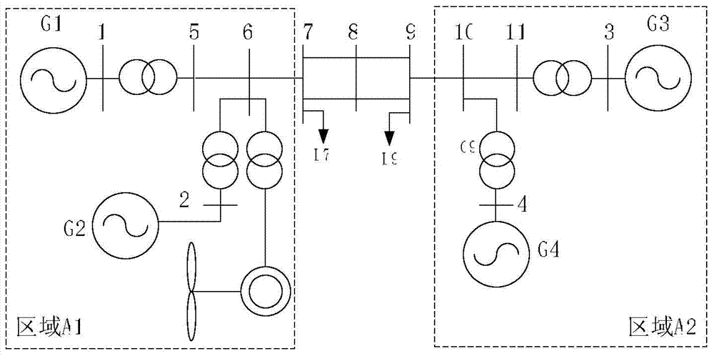

Image

  • Method for using rotational kinetic energy of permanent magnet synchronous draught fan for improving electric system damping
  • Method for using rotational kinetic energy of permanent magnet synchronous draught fan for improving electric system damping
  • Method for using rotational kinetic energy of permanent magnet synchronous draught fan for improving electric system damping

Examples


Embodiment

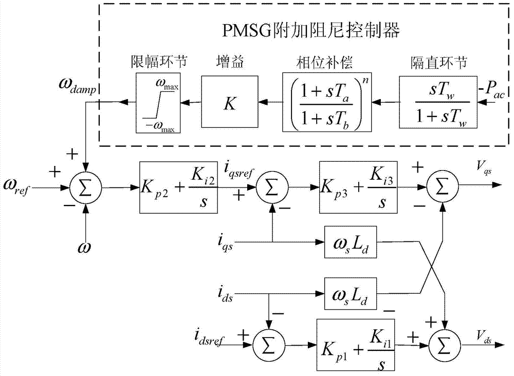
[0056] image 3 It is the control block diagram of the additional damping controller of the permanent magnet synchronous fan in the embodiment, image 3 It is shown that a specific implementation of the present invention is a method for improving the damping of the power system by using the rotational kinetic energy of the permanent magnet synchronous fan. The method is:

[0057] A. Identification of interregional oscillation modes

[0058] For the two-area power grid containing permanent magnet synchronous fans, the wide-area measurement system is used to measure the power signal of the tie line in real time, and the power signal sequence P ac , and then remove the DC component through data preprocessing to obtain the power fluctuation signal sequence ΔP ac , and then using the parameter estimation method based on the total least squares-rotation invariant subspace algorithm (TLS-ESPRIT), the power fluctuation signal sequence ΔP ac Carry out mode identification to identify...


PUM


Abstract

A method for using the rotational kinetic energy of a permanent magnet synchronous draught fan for improving electric system damping comprises the following steps: step A, a parameter estimation method of a total least squares-rotation invariant subspace algorithm is used for identifying an inter-area oscillation mode frequency omega d according to a power fluctuation signal delta Pac of a tie line; step B, under a perturbation, the phase angle difference phi 2 between a fan rotor speed omega and wind power Pd is measured, the phase angle difference between the wind power Pd and an inter-area inertia center angular frequency omega COI is phi 1, and a phase angle phi 3 which needs compensation is calculated, wherein the phi 3 is equal to the sum of the phi 1 and the phi 2; then, a phase compensation method is used for setting a first time constant Ta and a second time constant Tb in a phase compensation link and a gain factor K in a gain link in a supplementary damping controller for the permanent magnet synchronous draught fan; step C, an inversion signal -Pac of the tie line is input into the supplementary damping controller so as to output a signal to adjust the rotating speed of the draught fan, wherein the signal is a draught fan rotating speed adjustment signal omega damp; therefore, the rotational kinetic energy of the draught fan is used for improving the electric system damping.

Description

technical field [0001] The invention relates to a method for improving the damping of a power system by using the rotational kinetic energy of a permanent magnet synchronous fan. Background technique [0002] Vigorously developing wind power is an important development direction of my country's future energy strategy. At present, several large-scale wind power bases are being built in my country. The National Energy Administration issued the "Twelfth Five-Year Plan for Wind Power Development", which proposed the development goals, development layout and construction priorities of my country's wind power from 2011 to 2020. Among them, the planning of wind power in 2015 and The installed capacity of the grid will reach 100 million kilowatts, and it will exceed 200 million kilowatts by 2020. According to the national plan, focus on the construction of 9 large-scale wind power bases in Hebei, Eastern Mongolia, Western Mongolia, Jilin, Gansu, Shandong, Jiangsu, Xinjiang and Heilo...

Claims


Application Information

Patent Timeline
IPC IPC(8): H02J3/24H02P21/14
Inventor 王晓茹谭谨和鹏王祥超
Owner SOUTHWEST JIAOTONG UNIV
Learn More