Portable electronic equipment with vision caring function

一种电子设备、便携式的技术,应用在便携式电子设备领域,能够解决无法精确创造显像距离等问题,达到改善近视的效果

Active Publication Date: 2014-01-08
吴荣泰
View PDF11 Cites 0 Cited by
  • Summary
  • Abstract
  • Description
  • Claims
  • Application Information

AI Technical Summary

Problems solved by technology

The above-mentioned device has no actual understanding of the specifications of the optical lens. It only moves the image back and forth, and cannot really accurately create the actual required imaging distance, nor does it have the function of guiding the extraocular muscles to exercise properly

Method used


Image

  • Portable electronic equipment with vision caring function
  • Portable electronic equipment with vision caring function
  • Portable electronic equipment with vision caring function

Examples


Embodiment 1-1

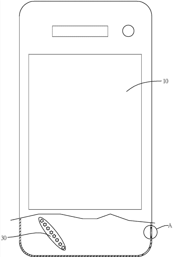
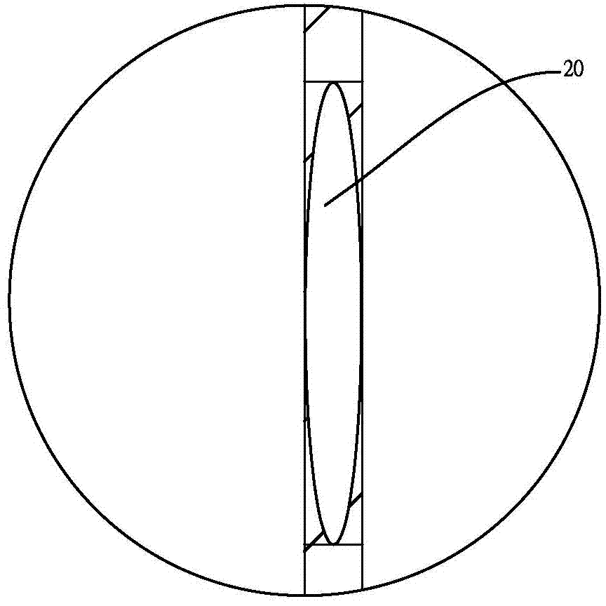
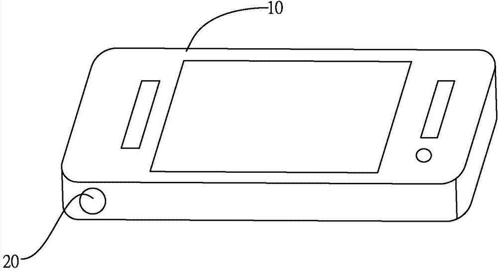
[0061] Embodiment 1-1, the present invention utilizes optical principle such as Figure 4 As shown, take a convex lens with a focal length of 0.4 cm as an example, and Figure 5a with Figure 5b The image display assembly 30 that moves back and forth is shown. The image display assembly 30 is inclined to the optical lens assembly 20. At this time, the LED light is used as the light source 32. The light source carrier 31 is provided with a plurality of light sources 32. The human eyes 40 are placed on the optical lens assembly 20. Observe the light source 32 of the image display unit 30 from one side of the light source carrier 31 and flash from far to near sequentially along a straight line. When the flashing image (object distance u) is located at 0.4cm, an infinite display can be displayed. Image distance; when the shiny image (object distance u) is at 0.3900cm, the image distance of 15.60cm can be displayed. Because the moving distance of the image (object distance u) is ...

Embodiment 1-2

[0065] Embodiment 1-2, the present invention utilizes optical principle such as Figure 4 As shown, taking a convex lens with a focal length of 40cm as an example, and as Figure 5a with Figure 5b The image display assembly 30 that moves back and forth is shown. The image display assembly 30 is inclined to the optical lens assembly 20. At this time, the LED light is used as the light source 32. The light source carrier 31 is provided with a plurality of light sources 32. The human eyes 40 are placed on the optical lens assembly 20. Observe from one side of the image display unit 30 that the light source 32 of the light source carrier 31 flashes from far to near in sequence along a straight line. When the light source 32 flashes on the light source carrier 31 (object distance u) is located at 40cm, The image distance of infinity can be displayed; when the shining image (object distance u) of the light source 32 on the light source carrier 31 is located at 11.0 cm, the image d...

Embodiment 2-1

[0069] Embodiment 2-1, the present invention utilizes optical principles such as Figure 4 As shown, taking a convex lens with a focal length of 10 cm as an example, the image display assembly 30 is parallel to the optical lens assembly 20. At this time, LED lights are used as the light source 32, and a plurality of light sources 32 are arranged on the upper circumference of the light source carrier 31. The image display assembly 30 The distance between the image on the light source carrier 31 is 6.67cm from the convex center point, and the image distance of 20.03cm in front can be displayed. Figure 6a with Figure 6b As shown, when the image on the light source carrier 31 of the image display unit 30 flickers counterclockwise, the eyeballs are guided to move according to their orientation, and the eyeballs can perform circular coordinated movements to provide the exercise effect of the six muscle groups. Specific embodiments The data are shown in Table 3.

[0070] table 3:...


PUM


Abstract

The invention discloses portable electronic equipment with the vision caring function. The portable electronic equipment comprises a portable electronic equipment body, an optical lens module, a control unit and an image display module, wherein a containing chamber isolating external light is arranged in the electronic equipment body, an opening is formed in the an outer case of the electronic equipment body, the optical lens module is arranged on the opening, communicated with the containing chamber, in the electronic equipment body, the control unit is arranged in the electronic equipment body, the image display module is arranged in the electronic equipment body and the containing chamber, corresponds to the optical lens module, and is controlled by the control unit, and the image display module is a light source or a light source module arranged on a light source carrier or an image screen. The image display module is arranged in the portable electronic equipment, the electronic equipment is convenient to carry, users can use the electronic equipment at any time to care and relax eyes, and the problems of myopia and astigmatism can be solved.

Description

【Technical field】 [0001] The invention relates to a portable electronic device with the function of protecting eyesight, which is equipped with a device for guiding eyeball movement, especially refers to using optical principles to manufacture far, near, up, down, left and right images with optical lenses and image display components. And circular movement, you can train the ciliary muscle at any time to achieve tension and relaxation exercises, guide eyeball movement, and enable the eye muscles to perform retraction and coordination functions. 【Background technique】 [0002] The muscles of the eyes are like rubber bands, they are stimulated by tension and relaxation to maintain the elasticity of the muscles. If it is tense or relaxed for a long time, it is easy to cause the eyesight to deteriorate. [0003] When the eyes look at nearby objects, they need to tighten the ciliary muscle to achieve a close focal length. Once the ciliary muscle relaxes and loses its elasticity,...

Claims


Application Information

Patent Timeline
Patent Type & Authority Applications(China)
IPC IPC(8): A61H5/00
CPCA61H5/00A61B3/005A61B3/02A61H2201/0153A61H2201/50A61H2201/5043
Inventor 吴荣泰
Owner 吴荣泰
Why Eureka
Try Eureka