Lock body automatic machining device

An automatic processing and lock body technology, which is applied in metal processing equipment, metal processing, measuring/indicating equipment, etc., can solve the problems of inability to guarantee the concentricity of holes, increase the labor intensity of operators, and reduce production efficiency, etc., to achieve structural Simple, reduce labor intensity and improve production efficiency

Active Publication Date: 2014-01-08
余欣
View PDF9 Cites 18 Cited by
  • Summary
  • Abstract
  • Description
  • Claims
  • Application Information

AI Technical Summary

Problems solved by technology

At present, the structure of the existing pin locks all includes lock body, lock cylinder, pin and other components, wherein the lock body is an important part of the structure of the pin lock, because the surface of the lock body is radially distributed with several holes and grooves, and the holes The necessary concentricity needs to be maintained between the holes, so the existing one-by-one processing method cannot guarantee the concentricity between the holes. The labor intensity greatly reduces the production efficiency

Method used


Image

  • Lock body automatic machining device
  • Lock body automatic machining device
  • Lock body automatic machining device

Examples


Embodiment Construction

[0026] The specific implementation manner of the present invention will be described below in conjunction with the accompanying drawings.

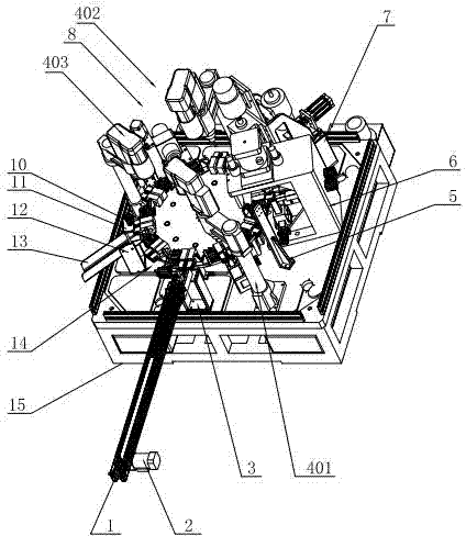
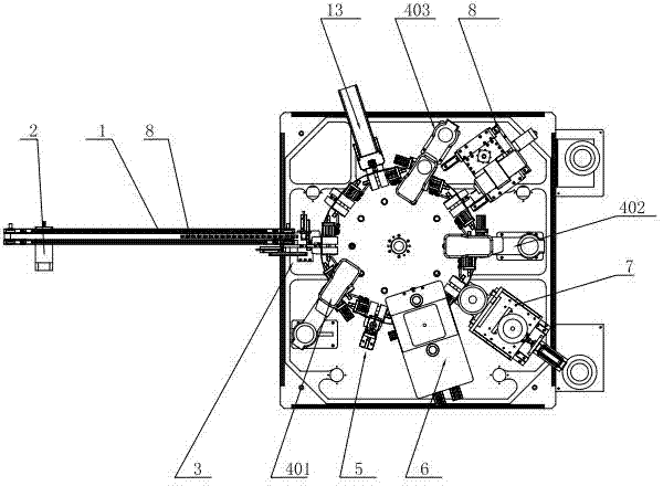
[0027] Such as figure 1 , figure 2 As shown, the present invention includes a frame 15 and a rotating disk assembly arranged on the frame 15, and multiple sets of positioning clamping units 14 are arranged along the circumferential direction of the rotating disk assembly, located on the frame 15, and positioned on the rotating disk assembly. On the outer periphery, arrange and position the feeding unit 3, the first automatic drilling unit 401, the hole position automatic detection unit 5, the automatic punching unit 6, the automatic milling unit 7, the second automatic drilling unit 402, and the small hole along the counterclockwise direction. The automatic processing unit 8, the third automatic drilling unit 403 and the discharging unit.

[0028] Such as Figure 4 As shown, the rotating disk assembly includes a total motor 16 installe...


PUM


Abstract

The invention relates to a lock body automatic machining device which comprises a machine frame and a rotation disc component arranged on the machine frame. A plurality of sets of locating and clamping units are arranged in the circumferential direction of the rotation disc component and located on the machine frame. The periphery of the rotation disc component is provided with a locating feeding unit, a first automatic drilling unit, a hole position automatic detection unit, an automatic notching unit, an automatic groove milling unit, a second automatic drilling unit, a small hole automatic machining unit, a third automatic drilling unit and a discharging unit in the anticlockwise direction. The lock body automatic machining device is simple in structure and convenient to operate, whole-journey automation of lock body machining is achieved, concentricity of central hole forming of the lock body is guaranteed, meanwhile groove machining is achieved at one time, groove accuracy is guaranteed, production efficiency is greatly improved, labor intensity is lowered, cost is saved for enterprise production, and enterprise production efficiency is improved.

Description

technical field [0001] The invention relates to lock body processing equipment, in particular to an automatic processing device for a pin lock body. Background technique [0002] Pin locks, also known as pinball locks, bead locks, bolster locks, or pin locks, are one of the most common lock constructions. The principle is to use several cylindrical parts of different heights (called shackles, pins or beads) to lock the cylinder. When the correct key is put in, each lock bolt is pushed to the same height, and the lock cylinder is released. At present, the structure of the existing pin locks all includes lock body, lock cylinder, pin and other components, wherein the lock body is an important part of the structure of the pin lock, because the surface of the lock body is radially distributed with several holes and grooves, and the holes The necessary concentricity needs to be maintained between the holes, so the existing one-by-one processing method cannot guarantee the conce...

Claims


Application Information

Patent Timeline
Patent Type & Authority Applications(China)
IPC IPC(8): B23P23/00B23Q7/00B23Q17/20
CPCB23P23/02
Inventor 董仲伟周建武
Owner 余欣
Why Eureka
Try Eureka