Supercharge Your Innovation With Domain-Expert AI Agents!

Swivel cab

A driver's cab and rotary technology, which is applied in the direction of mechanical equipment, load suspension components, gear transmissions, etc., can solve the problems of manufacturing personnel difficulties, increase production costs, etc., and achieve the effects of simple structure, extended service life, and simple maintenance

Active Publication Date: 2015-08-19
SUNWARD INTELLIGENT EQUIP CO LTD
View PDF5 Cites 0 Cited by
  • Summary
  • Abstract
  • Description
  • Claims
  • Application Information

AI Technical Summary

Problems solved by technology

Therefore, the supporting structure of the driver's cab must be compact, safe and flexible, and at the same time, it must not bring difficulties to the manufacturing personnel and increase production costs.

Method used


Image

  • Swivel cab
  • Swivel cab

Examples


Embodiment Construction

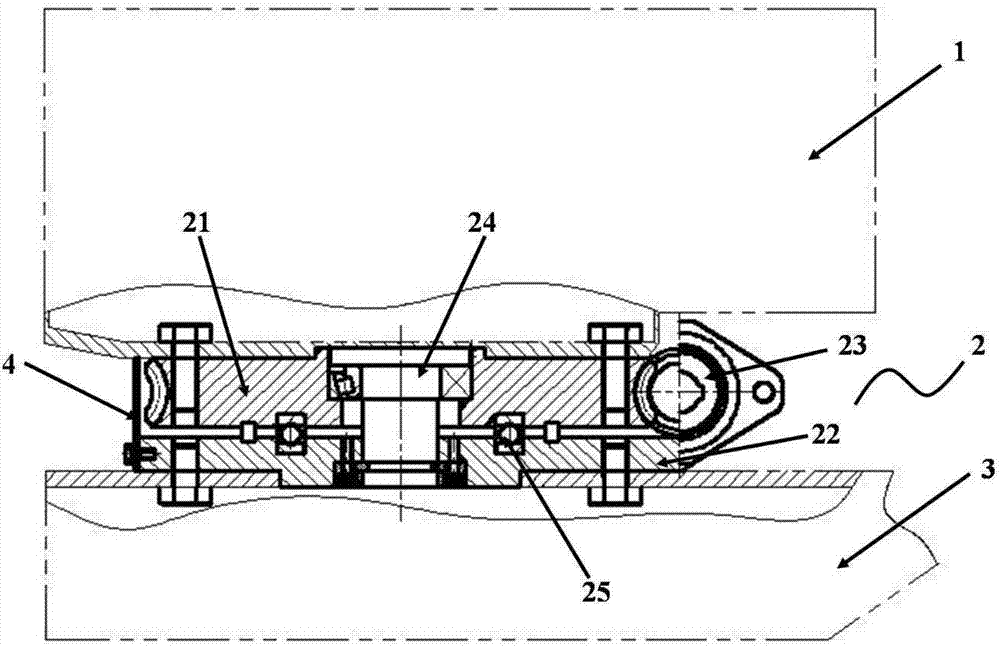
[0028] Such as figure 1 , 2 As shown, this embodiment provides a rotary driver's cab, including a driver's cab 1, a rotary drive device 2 located below the driver's cab 1, and a bracket 3 below the rotary drive device 2;

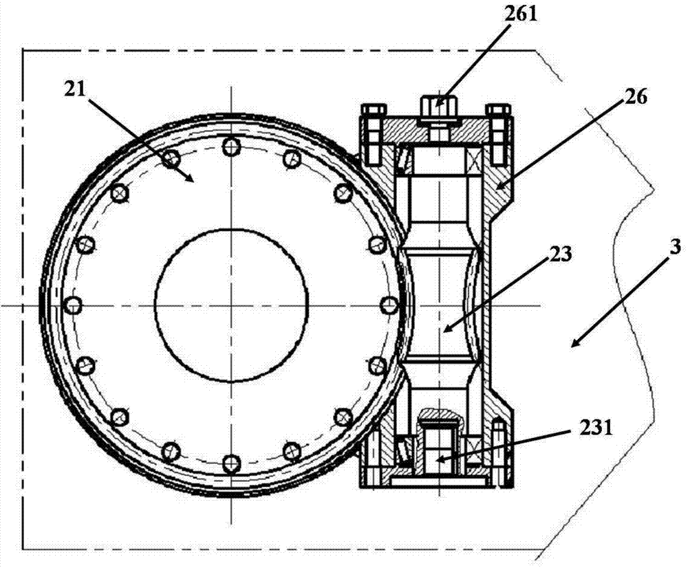
[0029] The rotary driving device 2 includes a worm wheel 21, a lower support 22 and a worm screw 23, the worm wheel 21 and the lower support 22 are connected by a central shaft 24, and the central shaft 24 passes through the first shaft hole at the center of the worm wheel 21 In the second shaft hole at the corresponding position of the lower support 22, the bottom surface of the worm wheel 21 and the top surface of the lower support 22 are parallel to each other, and there is a thrust force between the worm wheel 21 and the lower support 22. The ball bearing 25 avoids direct friction between the lower surface of the worm wheel 21 and the upper surface of the lower support 22;

[0030] The worm 23 is located in the installation groove 26 on the right side ...


PUM


Abstract

The invention provides a rotary cab. The rotary cab comprises a cab body, a rotary driving device below the cab body, and a support below the rotary driving device, wherein the rotary driving device comprises a worm wheel, a lower support and a worm; the worm wheel is connected with the lower support through a middle shaft, the middle shaft passes through a first shaft hole in the circle center of the worm wheel and extends into a second shaft hole in the corresponding position of the lower support, and the bottom surface of the worm is parallel with the top surface of the lower support; a thrust ball bearing is also arranged between the worm wheel and the lower support, and a rod body of the worm is meshed with the outer edge of the worm wheel. The rotary cab provided by the invention can rotate in a horizontal plane at 360 degrees and has the advantages of simple structure, flexibility in rotation and high transmission efficiency.

Description

technical field [0001] The invention relates to a rotary driver's cab, which belongs to the technical field of construction machinery, and in particular provides a safe and flexible relative rotation between a crane driver's cab and a support. Background technique [0002] With the rapid development of my country's economic construction, the market demand for construction machinery is increasing day by day, and the development of construction hoisting machinery has ushered in an era full of vitality and innovation. [0003] In recent years, large-tonnage cranes have begun to enter the stage of history. However, the integrated design of the traditional cab and driver's cab cannot meet the operating requirements of large-tonnage cranes. When large-tonnage cranes are in operation, the cab for lifting operations needs to be separated from the structure of the crane. [0004] In view of the need for convenient operation, the driver's cab of a large-tonnage crane must be able to ...

Claims


Application Information

Patent Timeline
Patent Type & Authority Patents(China)
IPC IPC(8): B66C13/54F16H1/16
Inventor 袁德鹏卢青梅刘子强
Owner SUNWARD INTELLIGENT EQUIP CO LTD
Features
  • R&D
  • Intellectual Property
  • Life Sciences
  • Materials
  • Tech Scout
  • Unparalleled Data Quality
  • Higher Quality Content
  • 60% Fewer Hallucinations
Learn More