
End face deformation measuring device for face milling cutter based on dual-pulse laser

A measuring device and double-pulse technology, applied in the direction of measuring devices, optical devices, instruments, etc., can solve the problem of lack of tool end face deformation measurement, and achieve the effect of strong vibration resistance

Active Publication Date: 2014-01-08
徐州锐尔五金工具制造有限公司
View PDF4 Cites 2 Cited by
  • Summary
  • Abstract
  • Description
  • Claims
  • Application Information

AI Technical Summary

Problems solved by technology

Due to the limitation of measurement methods and measuring instruments, there are few researches on stress measurement devices for the comprehensive strain stress field of face milling cutters in high-speed cutting at home and abroad, especially the lack of devices that can measure the deformation of the tool end surface without contacting the tool surface

Method used


Image

  • End face deformation measuring device for face milling cutter based on dual-pulse laser
  • End face deformation measuring device for face milling cutter based on dual-pulse laser
  • End face deformation measuring device for face milling cutter based on dual-pulse laser

Examples


Embodiment Construction

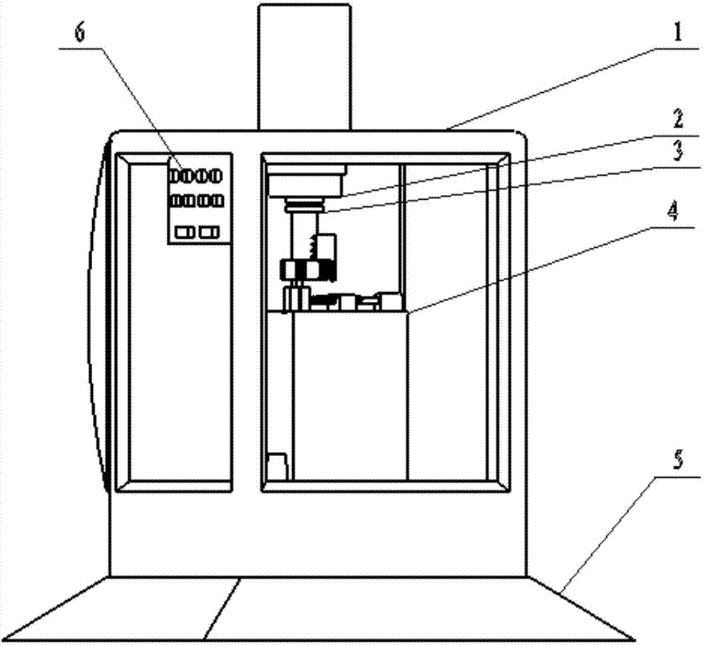
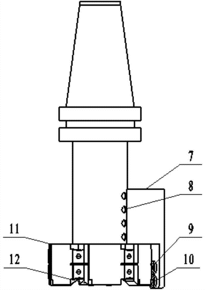
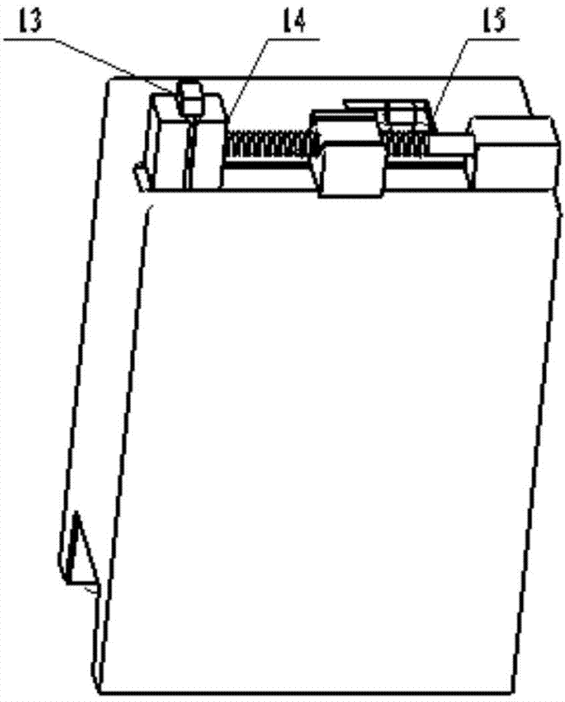
[0010] As shown in the figure, a face milling tool end face deformation measurement device based on a double pulse laser consists of a spindle box 1, an electric spindle 2, a connecting tool bar 3, a fixed platform 4, a base 5, a controller 6, and a double pulse laser 7 , set bolt 8, laser emitting end 9, CCD lens 10, face milling cutter head 11, milling cutter 12, milling workpiece 13, clamping device 14, ball screw 15; it is characterized in that: spindle box 1 is connected with base 5 Together, the electric spindle 2 and the controller 6 are fixed on the upper end of the spindle box 1, the electric spindle 2 is equipped with the connecting knife bar 3, and the double pulse laser 7 is firmly fixed on the connecting knife bar 3 through the tightening bolt 8, and the double pulse A laser emitting end 9 and a CCD lens 10 are installed on the laser 7, a face milling cutter disc 11 is installed on the connecting tool bar 3, a milling cutter 12 is provided on the face milling cutte...


PUM


Abstract

The invention discloses an end face deformation measuring device for a face milling cutter based on a dual-pulse laser. The end face deformation measuring device consists of a spindle box, an electric main shaft, a cutter connecting rod, a fixed platform, a base, a controller, a dual-pulse laser, a fastening bolt, a laser emitting end, a CCD (Charge Coupled Device) lens, a face milling cutter disk, a milling cutter, a milling workpiece, a clamping device and a ball screw, wherein the main spindle box is connected with the base; the electric main shaft and the controller are fixed at the upper end of the main spindle box; the cutter connecting rod is arranged on the electric main shaft; the dual-pulse laser is fixed on the cutter connecting rod through the fastening bolt; the laser emitting end and the CCD lens are arranged on the dual-pulse laser; the face milling cutter disk is arranged on the cutter connecting rod; the milling cutter is arranged on the face milling cutter disk; the milling workpiece is clamped on the clamping device; the fixed platform is arranged at the lower end of the main spindle box; the clamping device and the ball screw rod are arranged on the fixed platform. According to the measuring device, a small-sized measuring system is arranged on the cutter connecting rod rotating at a high speed, so that high-speed dynamic measurement is converted into quasi-state measurement, and the advantages of freeness from contact, high accuracy, high vibration resistance and the like are achieved.

Description

technical field [0001] The invention relates to a face milling tool end face deformation measuring device based on a double pulse laser, specifically, a face milling tool composed of a spindle box, an electric spindle, a double pulse laser, a face milling cutter disc, etc. end-face deformation measuring device. Background technique [0002] High-speed cutting technology is becoming the mainstream of cutting processing. In the process of high-speed cutting, tool stress distribution directly affects the reliability and cutting performance of the tool. When cutting at high speed, the main form of tool damage of face milling cutter is breakage. The main cause of tool damage is the result of various stresses such as mechanical stress and thermal stress. Under different cutting conditions, mechanical stress and thermal stress are mutually dominant to cause damage to cutting tools. Due to the limitation of measurement methods and measuring instruments, there are few researches on...

Claims


Application Information

Patent Timeline
Patent Type & Authority Applications(China)
IPC IPC(8): G01B11/16
Inventor 李腾飞于复生张荣禄
Owner 徐州锐尔五金工具制造有限公司
Learn More