
Improved structure for improving detection accuracy of clinical in vitro detection analyzer

A technology with improved structure and detection accuracy, applied in the field of clinical medical devices, can solve the problems of poor consistency of the thickness of the tray chassis, great influence on the detection accuracy, and insufficient accuracy of the detection results, and achieve the effect of obvious improvement effect, small investment and increased cost.

Active Publication Date: 2015-07-15
SHANGHAI UPPER BIO TECH PHARMA
View PDF7 Cites 0 Cited by
  • Summary
  • Abstract
  • Description
  • Claims
  • Application Information

AI Technical Summary

Problems solved by technology

[0003] The clinical in vitro detection analyzers currently on the market generally have a sample loading tray with a reaction plate. The reaction plate is placed on the sample loading tray and moves to the bottom of the detection head with the sample loading tray. The sample liquid is photographed, and the detection result is automatically judged by the color of the sample liquid. The sample loading tray has continuous loading patterns, and there are also one-by-one loading styles. The sample loading methods all use the sample loading tray, which has a common disadvantage: the distance between the built-in CCD of the detection head and the reaction plate has a great influence on the detection accuracy, so due to the instability of the distance, the accuracy of the detection results is insufficient
There are many possibilities for this to happen, for example, the thickness consistency of the sample tray chassis is poor, the sample tray may move slightly on the slide rail, etc.

Method used


Image

  • Improved structure for improving detection accuracy of clinical in vitro detection analyzer
  • Improved structure for improving detection accuracy of clinical in vitro detection analyzer
  • Improved structure for improving detection accuracy of clinical in vitro detection analyzer

Examples


Embodiment

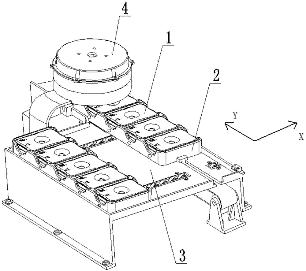
[0026] Embodiment (one): see figure 1 , Figure 1 It shows a sample loading system of a clinical in vitro detection analyzer. There are five places for placing reaction plates 1 in the sample loading tray 2. The reaction plate 1 is placed in the sample loading tray 2 and first moves along the X direction with the sample loading tray. Moving along the Y direction, the reaction plates 1 pass under the detection head 4 one by one for detection.

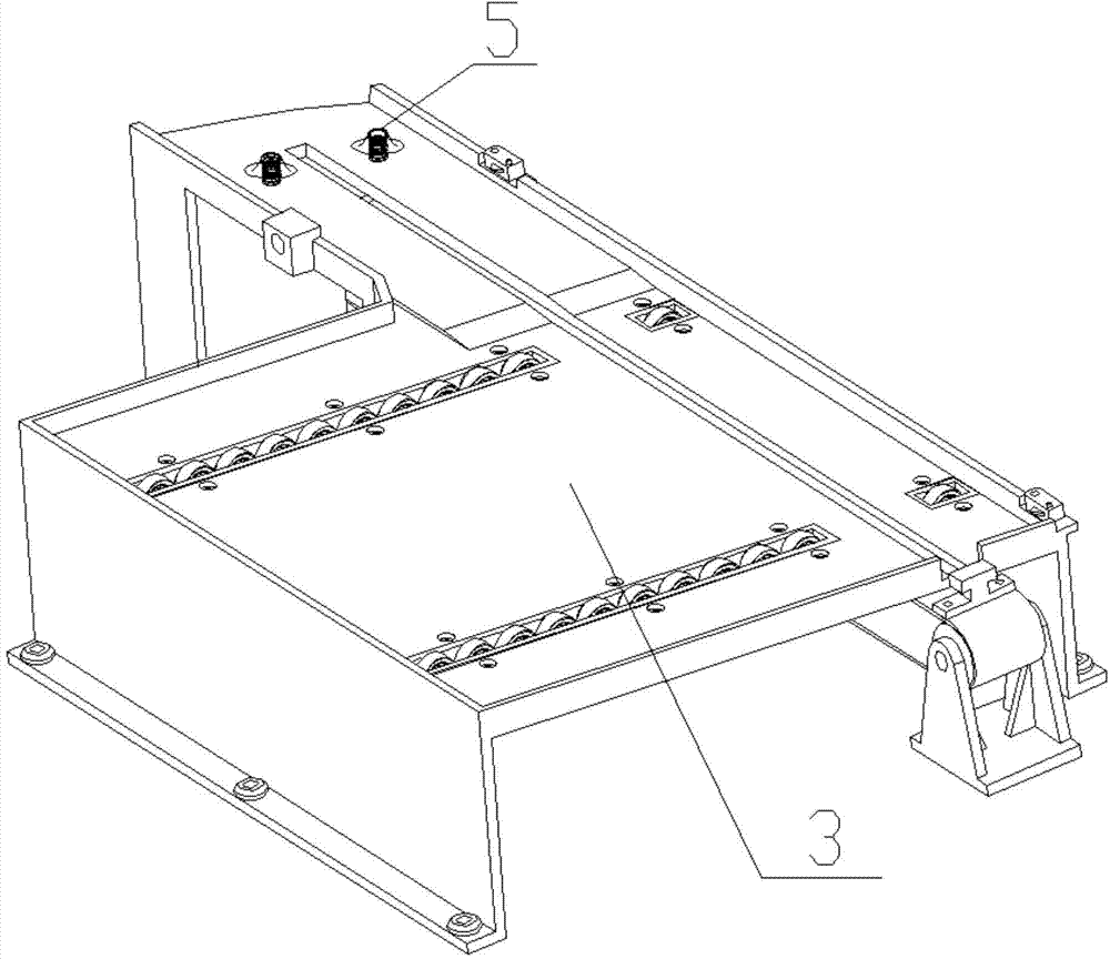
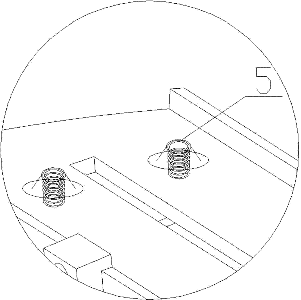
[0027] see Figure 2-3 , on the slideway plate, two elastic jacking bosses 5 are fixedly arranged at positions corresponding to the lower part of the detection head 4, and the elastic jacking bosses 5 are composed of a spring and a truncated circular buckle cap located above the spring, the buckle cap It is welded and fixed with the upper end of the spring, the spring passes through the hole opened on the slideway plate, and the lower part of the spring is positioned and fixed.

[0028] see Figure 4 , at the bottom of each reaction ...

Embodiment ( 2

[0031] see together Figure 5-6 , Figure 9 , the difference from embodiment (1) is that a solenoid valve is used as the power device, and the ejector rod of the solenoid valve corresponds to the hole 2a at the bottom of the sample loading tray 2. When the sample loading tray 2 passes under the detection head 4, When the solenoid valve is energized, its ejector rod will push up the reaction plate 1, which can also ensure the distance between the reaction plate and the CCD of the detection head, and ensure the detection accuracy and stability. The advantages of using solenoid valves are high reliability, relatively high stability and precision.

Embodiment ( 3

[0033] The difference between this embodiment and embodiment (1) is that, see Figure 7 , the spring piece 6 is used as the elastic jacking boss, and the spring piece 6 is directly arranged on the slideway plate. The front end of the spring piece is welded or riveted with the slideway plate, and the rear end is tilted up. Diameter of hole 2a; see Figure 8 , when the sample loading tray slides above the spring piece, the spring piece 6 just fits into the hole 2a and lifts up the reaction plate 1; see Figure 9 , when the spring piece 6 leaves the position of the hole 2a, but is still pressed by the sample loading tray 2, the spring piece is pressed into a horizontal configuration. The advantage of using the spring piece 6 as the elastic jacking boss is that the structure is simple, and no holes are needed on the slideway plate.

[0034] The above three embodiments are only preferred embodiments for solving the technical problems of the present invention. In actual situations...


PUM


Abstract

The invention relates to an improved structure for improving the detection accuracy of a clinical in vitro detection analyzer. The improved structure comprises a detection head and a sample feeding tray, wherein a bottom tray of the sample feeding tray is provided with holes; elastic / power jacking bosses are fixedly arranged under the detection head; when a reaction plate in the sample feeding tray is jacked upwards by the elastic / power jacking bosses, a fixed distance is reserved between the reaction plate and the detection head. The distance between a charge coupled device (CCD) of the detection head and sample liquid in the reaction plate is not stable, so that the shooting effect of the CCD is influenced, and the accuracy of a detection result is unstable. In order to solve the technical problem, the elastic / power jacking bosses are arranged under the detection head, the bottom of the sample feeding tray is provided with the holes, and the reaction plate is jacked upwards by the elastic / power jacking bosses which pass through the holes; the thickness accuracy of the reaction plate is generally high, so that the consistency of the distances between the detection head and all reaction plates which pass through the detection head can be guaranteed only by guaranteeing the consistency of the upward jacking distances of the reaction plates; therefore, the shooting effect of the CCD is guaranteed, and the detection accuracy is further guaranteed.

Description

technical field [0001] The invention relates to a clinical in vitro detection analyzer, in particular to an improved structure for improving the detection accuracy of the clinical in vitro detection analyzer, which belongs to the technical field of clinical medical devices. Background technique [0002] POCT, point-of-care testing, refers to the clinical testing performed next to the patient. It is a type of immediate analysis at the sampling site, which saves the complicated processing procedures of specimens in the laboratory and quickly obtains test results. new method. The main criteria of POCT are that no fixed testing site is required, reagents and instruments are portable, and can be operated in a timely manner. In recent years, due to the development of today's high-tech and medical science, as well as efficient and fast-paced working methods, POCT, which has the advantages of miniaturization of experimental instruments, simple operation, and instant report results,...

Claims


Application Information

Patent Timeline
Patent Type & Authority Patents(China)
IPC IPC(8): G01N21/25
Inventor 王钧黄剑峰
Owner SHANGHAI UPPER BIO TECH PHARMA
Learn More