Diode testing device and use method thereof

A test device, diode technology, applied in the direction of measuring device shell, single semiconductor device test, etc., can solve the problems of test data error, loose fixation, mechanical damage, etc., achieve stable and reliable data, improve test reliability, and reduce damage Effect

Active Publication Date: 2014-01-08
GUIZHOU AEROSPACE INST OF MEASURING & TESTING TECH
View PDF6 Cites 10 Cited by
  • Summary
  • Abstract
  • Description
  • Claims
  • Application Information

AI Technical Summary

Problems solved by technology

[0003]Technical problem to be solved by the present invention: Provide a diode test device and its use method to solve the problem of using conventional clamping when testing ultra-fine pin axially packaged diodes Or the mechanical damage, poor contact, loose fixation caused by the press-fit test method, which may easily cause large test data errors, etc.

Method used


Image

  • Diode testing device and use method thereof
  • Diode testing device and use method thereof
  • Diode testing device and use method thereof

Examples


Embodiment

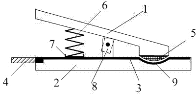
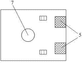
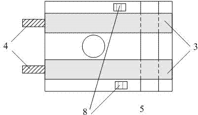
[0019] A diode testing device, which includes an upper splint 1, a lower splint 2 and two metal electrodes 3, the two metal electrodes 3 are electrically connected to two terminal posts 4 at the left end of the lower splint 2, and there are springs 6 and supports between the upper and lower splints Column 8, the right end of the lower splint 2 has a groove 9, and the right end of the upper splint 1 has two protrusions 5, and the protrusions 5 are placed in the groove 9 。

[0020] The groove 9 is arc-shaped, and the shape of the protrusion 5 corresponds to the shape of the groove 9 and has the same size, so as to ensure that the protrusion 5 can be in close contact with the groove 9 .

[0021] The protrusion 5 adopts an elastic rubber protrusion to ensure that the pins of the diode are not damaged while crimping the diode under test.

[0022] The width of the groove 9 is 10-15 times the diameter of the tested diode shell, and the depth is 3-5 times the diameter of the tested d...


PUM


Abstract

The invention discloses a diode testing device, which comprises an upper clamping plate (1), a lower clamping plate (2) and two metal electrodes (3), wherein the two metal electrodes (3) are connected with two wiring terminals (4) at the left end of the lower clamping plate (2), and a spring (6) and support columns (8) are arranged between the upper clamping plate and the lower clamping plate. The diode testing device is characterized in that the right end of the lower clamping plate (2) is provided with a groove (9), the right end of the upper clamping plate (1) is provided with two protrusions (5), and the protrusions (5) are arranged in the groove (9). The device solves the problems of mechanical damage, poor contact, unfirm fixing, easy forming of large error of testing data and the like of the conventional clamping or crimping testing method when a diode, especially a superfine pin axial packaging diode, is tested.

Description

Technical field [0001] The present invention belongs to the field of diode testing technology, and especially involves a kind of fine -drawn diode testing device and its usage. Background technique [0002] The diodes of the axis encapsulation of the pole have two pins with a diameter of less than 0.2mm. The pins are mostly made of flexible metal materials, which is easily damaged.At present, there are two main methods for testing the diodes of this extremely detailed foot axis packaging. One is to use ordinary crocodile clamps to directly clamp the two -ends of the diodes for testing. Because this diode pin is extremely thin and softer, this is softer. This is softer. This is soft.Methods can easily cause pins or even break.Another method is to press the two pins on a smooth metal electrode to test. Although this method is less damage to the pins, because this diode pin is mostly bent, the diodes pins and metal often appear.Poor electrode contact causes the problem of super poor...

Claims


Application Information

Patent Timeline
Patent Type & Authority Applications(China)
IPC IPC(8): G01R31/26G01R1/04
Inventor 邱云峰袁文张文辉雷芸
Owner GUIZHOU AEROSPACE INST OF MEASURING & TESTING TECH
Why Eureka
Try Eureka