Water pump pressure switch

A water pump pressure and switch technology, which is applied in the field of water pump control switch improvement, can solve the problems of affecting spring size, expensive manufacturing cost, pressure error, etc., and achieve the effect of stable operation, high precision and low cost

Active Publication Date: 2014-01-08
JIANGSU HUANLI TECH DEV CO LTD
View PDF7 Cites 6 Cited by
  • Summary
  • Abstract
  • Description
  • Claims
  • Application Information

AI Technical Summary

Problems solved by technology

[0003] The mechanical spring type water pump pressure switch is generally composed of a pressure spring, a spring seat, and a micro switch. If the pressure control point needs to be displayed directly, other display components need to be added. The principle is: the water pressure generated by the water pump makes the spring Deformation, so that the position of the spring seat changes to activate the micro switch, and finally control the on-off of the circuit, but due to the material and performance of the spring, the pressure range controlled by it is relatively small, and the ambient temperature changes greatly case, under long-term fatigue compression, ultimately affects the size of the spring, causing pressure errors over time
[0004] The control precision of the pressure sensor type water pump pressure switch is relatively high, and the controllable pressure range will be relatively wide, and the pressure value of the starting point can be set arbitrarily. It needs to cooperate with the display LCD or digital LED tube to display the control pressure point. But its manufacturing cost will be more expensive

Method used


Image

  • Water pump pressure switch
  • Water pump pressure switch
  • Water pump pressure switch

Examples


Embodiment Construction

[0035] The present invention will be further described in detail below in conjunction with the accompanying drawings and specific embodiments.

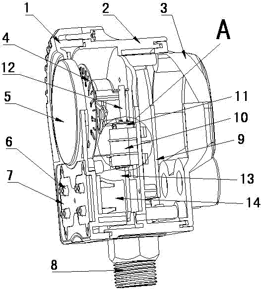
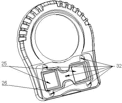
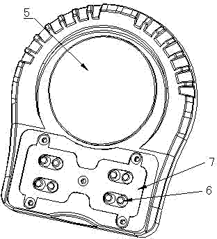
[0036] attached Figure 1-13 The water pump pressure switch according to the present invention includes a sealed housing; the sealed housing includes a middle body 2; a hollow metal threaded joint 8 extending outward is connected directly below the sealed housing, and the metal The threaded joint 8 is connected with the threaded hole 29 below the middle body 2 through the thread 30 at its end. The sealed housing includes a panel 1, a middle body 2, a lower cover 3, and a transparent window 5, wherein the transparent window 5 is connected to the panel. 1. It is connected as a whole by ultrasonic welding technology. There are two square through holes 25 on the panel 1. The square through holes 25 are used to install two dial switches 14. At the same time, the H-shaped groove 26 on the panel 1 is It is used to install the transparent ru...


PUM


Abstract

The invention discloses a water pump pressure switch, which comprises a sealed housing, wherein the lower part of the sealed housing is provided with a threaded joint, and transparent rubber keys capable of adjusting starting point and shut-down point pressure are arranged on a panel of the sealed housing; a signal circuit board assembly, a pressure gauge sensor assembly and a circuit board control module are arranged in the sealed housing, and DIP switches capable of setting starting and shut-down pressure points are arranged on the signal circuit board; the pressure gauge sensor assembly is provided with a pressure gauge, and the tail of a bourdon tube on the back of the pressure gauge is connected with a connecting strip; the tail of the connecting strip is connected with a magnetic steel seat, and two N-N magnetic steel pieces are arranged on the magnetic steel seat; and the magnetic steel seat is arranged on a magnetic steel seat support and can slide up and down in the magnetic steel seat support, and a linear Hall component is arranged on the circuit board control module and is positioned between the two N-N magnetic steel pieces. The water pump pressure switch provided by the invention has the advantages of high precision, low cost, stable operation and pressure display.

Description

technical field [0001] The invention relates to an improvement of a water pump control switch, in particular to a water pump pressure switch with high precision, low cost, stable operation and pressure display. Background technique [0002] At present, in the water pump controller industry, most of the pressure signals are used to control the start and stop of the water pump. There are two types of widely used ones: one is the mechanical spring type water pump pressure switch, which is controlled by the compression deformation of the mechanical spring. Control the pressure point, the other is the pressure sensor type water pump pressure switch, which controls the water pump by outputting the pressure control point signal through the pressure sensor, and finally meets the customer's use requirements, and provides water supply and drainage industry, water supply without tower, chemical industry and other industries A lot of convenience. [0003] The mechanical spring type wat...

Claims


Application Information

Patent Timeline
Patent Type & Authority Applications(China)
IPC IPC(8): H01H35/26H01H35/36F04B49/06
Inventor 陈佳妮徐利民张红军沈伟伟
Owner JIANGSU HUANLI TECH DEV CO LTD
Why Eureka
Try Eureka