Actuator arrangement for use in a fuel injector
A technology for actuator devices and fuel injectors, which is applied in the direction of fuel injection devices, special fuel injection devices, machines/engines, etc., to achieve the effect of avoiding poorly fixed interface
- Summary
- Abstract
- Description
- Claims
- Application Information
AI Technical Summary
Problems solved by technology
Method used
Image
Examples
Embodiment Construction
[0048] As shown in the side view of FIG. 1 , the actuator device 10 includes a generally cylindrical body portion 12 comprising a central body portion housing the piezoelectric stack structure, and first and second end pieces 14, 16, respectively. . At a first end of the body portion 12, the end piece 14 includes an electrical connector 18 having a first terminal 20 and a second terminal 22 for receiving a voltage from a voltage source. At a second end of the body portion 12, an end piece 16 includes a load transfer member, commonly referred to as a ball joint, for cooperating with a control piston or valve needle (not shown) of the fuel injector.
[0049] Details of the piezoelectric stack structure and internal components of the actuator 10 and a description of how the actuator operates have been fully disclosed in the applicant's granted patent EP0995901 and will therefore not be discussed here.
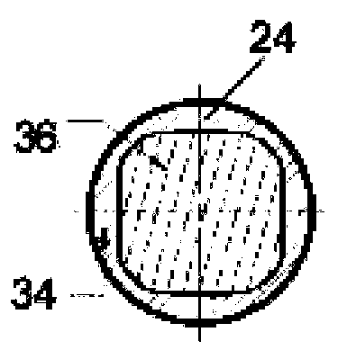
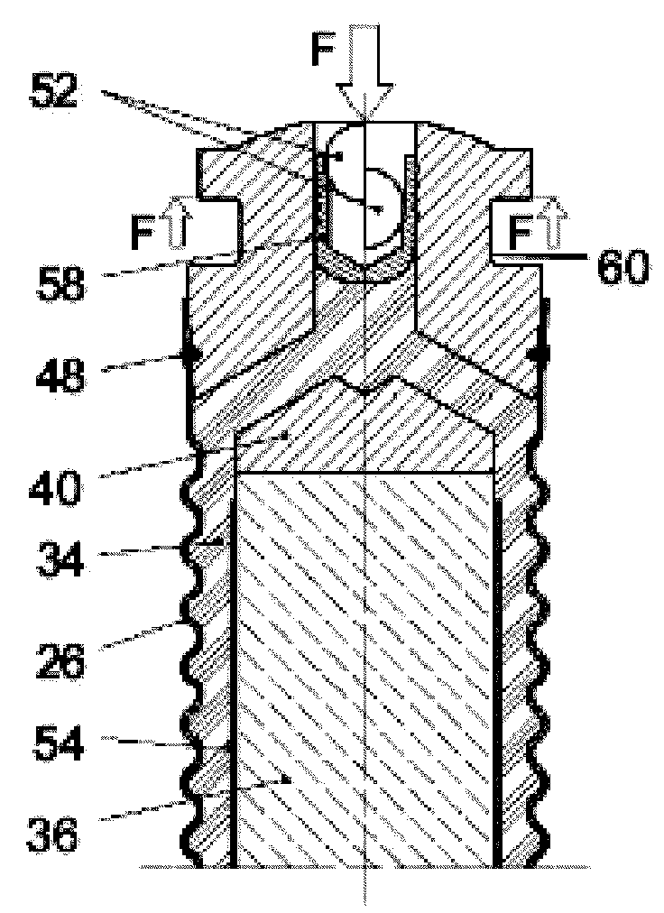
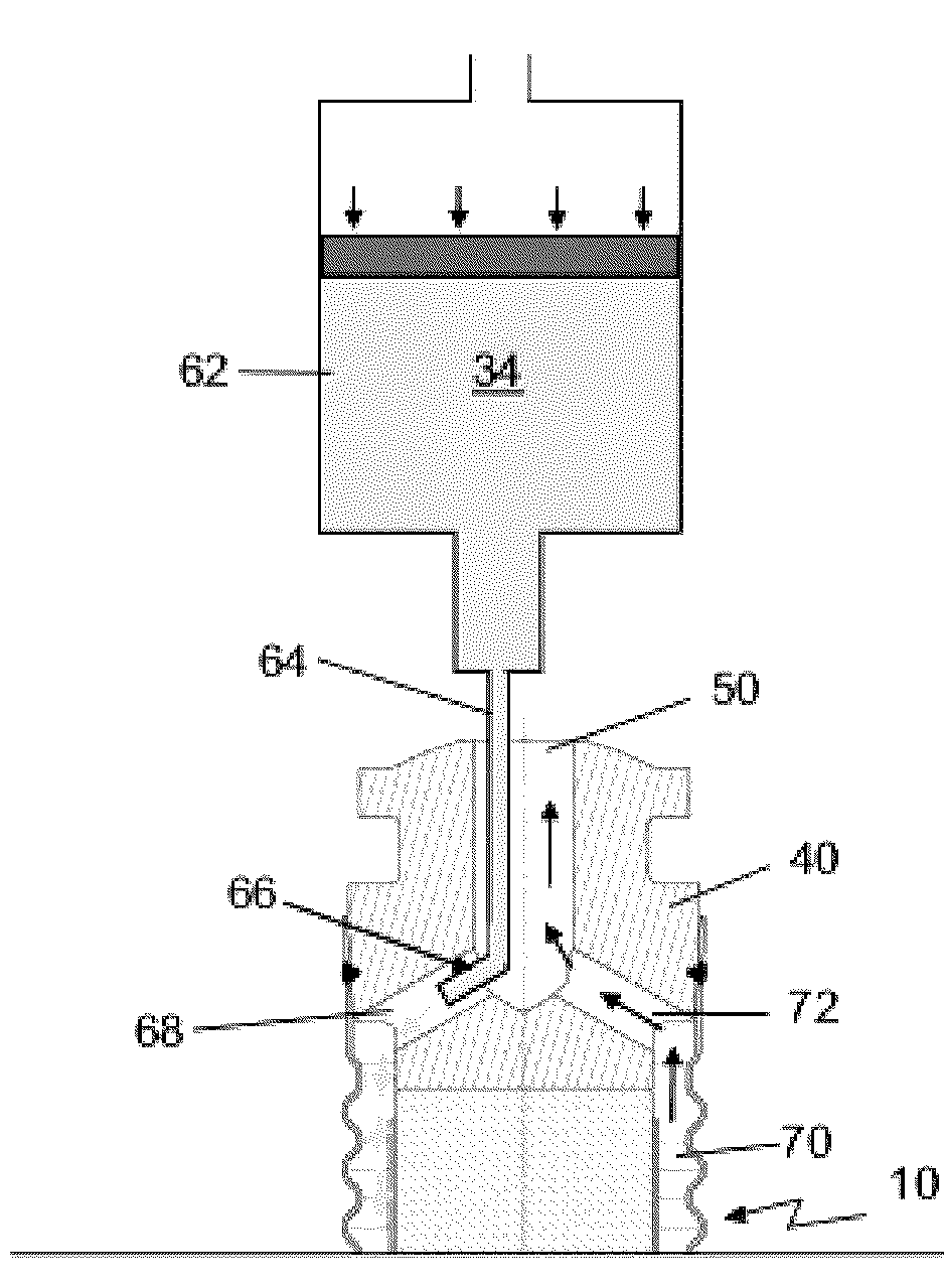
[0050] From FIG. 1 it is apparent that there is an encapsulation member 24 w...
PUM
| Property | Measurement | Unit |
|---|---|---|
| Thickness | aaaaa | aaaaa |
Abstract
Description
Claims
Application Information
 - R&D
- Intellectual Property
- Life Sciences
- Materials
- Tech Scout
- Unparalleled Data Quality
- Higher Quality Content
- 60% Fewer Hallucinations
Browse by: Latest US Patents, China's latest patents, Technical Efficacy Thesaurus, Application Domain, Technology Topic, Popular Technical Reports.
© 2025 PatSnap. All rights reserved.Legal|Privacy policy|Modern Slavery Act Transparency Statement|Sitemap|About US| Contact US: help@patsnap.com


