Iron section removing device and method used during iron section sand cladding casting of shuttle-type top plate

A technology of sand-covered iron casting and cleaning device, which is applied in the direction of casting molding equipment, cleaning/processing machinery of casting mold materials, molding machines, etc., to achieve the effects of improving utilization rate, reasonable structure design, and facilitating logistics layout

Active Publication Date: 2014-01-15
浙江省机电设计研究院有限公司
View PDF6 Cites 8 Cited by
  • Summary
  • Abstract
  • Description
  • Claims
  • Application Information

AI Technical Summary

Problems solved by technology

Although this patent can conveniently and efficiently remove the sand shooting hole of the iron mold and the residual sand in the inner cavity, so as to meet the production requirements of the iron mold sand-covered casting, but when the positions of the sand shooting holes of the upper and lower iron molds are inconsistent, two The iron type top hole cleaning machine is used to complete the top hole cleaning process of the upper iron type and the lower iron type respectively, so it still has the above defects

Method used


Image

  • Iron section removing device and method used during iron section sand cladding casting of shuttle-type top plate
  • Iron section removing device and method used during iron section sand cladding casting of shuttle-type top plate
  • Iron section removing device and method used during iron section sand cladding casting of shuttle-type top plate

Examples


Embodiment Construction

[0028] The present invention will be further described in detail below in conjunction with the accompanying drawings and examples. The following examples are explanations of the present invention and the present invention is not limited to the following examples.

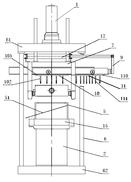
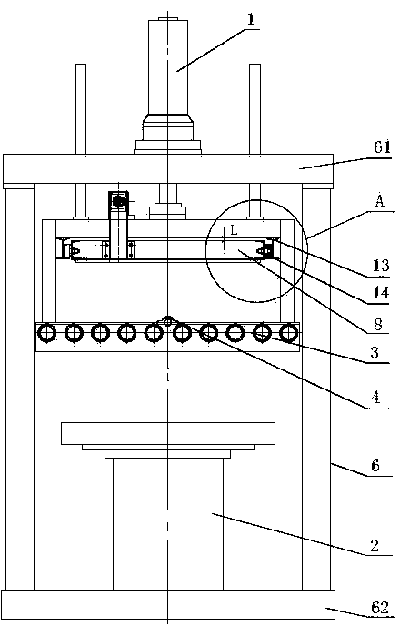
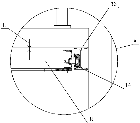
[0029] see Figure 1-Figure 7 , the present invention mainly includes ejection cylinder 1, vibrating device 2, iron type conveying roller table 3, iron type positioning device 4, sand falling bucket device 5, frame 6, moving beam 7, trolley body 8, trolley connecting plate 9 , Upper iron type ejector device 10, lower iron type ejector device 11, trolley cylinder 12, trolley guide rail 13, trolley moving wheel 14, workbench 15, upper iron type 16, lower iron type 17, upper top plate 101, upper top Rod 102 , lower top plate 110 , lower ejector rod 111 , slide plate 51 , upper beam 61 and base 62 .

[0030] The frame 6 in the present embodiment comprises an upper beam 61 and a base 62. The ejecting cylinder body 1 ado...


PUM


Abstract

The invention relates to an iron section removing device and an iron section removing method used during iron section sand cladding casting of a shuttle-type top plate, and belongs to the field of iron section sand cladding casting equipment. The iron section removing device comprises an ejecting cylinder, a vibrating device, an iron section conveying roller way, an iron section positioning device, a sand falling bucket device, a movable beam, a trolley body, a trolley connecting plate, an upper iron section ejecting device and a lower iron section ejecting device, wherein the movable beam is connected with a piston rod of the ejecting cylinder; the iron section positioning device is arranged in the middle of the iron section conveying roller way; a workbench is arranged on the vibrating device; the sand falling bucket device is fixed on the workbench; the trolley body is connected with the piston rod of a trolley cylinder through the trolley connecting plate; a gap is formed between the upper surface of the trolley body and the lower surface of the movable beam; the upper iron section ejecting device and the lower iron section ejecting device are arranged on the movable beam. The iron section removing device is used for removing the upper iron section and the lower iron section which are different in sand ejecting holes positions, thus meeting removal of iron section sand cladding of the upper iron section and the lower iron section with inconsistent positions of the sand ejecting holes.

Description

technical field [0001] The present invention relates to a device and a method, in particular to an iron mold cleaning device and method in the iron mold sand-covered casting of the shuttle roof, and one iron mold cleaning device is used to complete the upper iron mold with different shot hole positions. The utility model relates to the cleaning of molds and lower iron molds, which belongs to the field of iron mold sand-covered casting equipment. Background technique [0002] Iron mold sand-covered casting is one of the special castings. The mold is formed by covering the inner cavity of the metal mold with a thin layer of coated sand. The metal mold is called an iron mold; in the iron mold sand-coated casting production During the process, an upper iron mold and a lower iron mold are combined to form a complete casting mold. The sand coating layer on the upper and lower iron molds is formed by the sand shot molding machine through the sand shooting holes of the upper and low...

Claims


Application Information

Patent Timeline
Patent Type & Authority Applications(China)
IPC IPC(8): B22C5/00B22C15/23
Inventor 潘东杰黄列群何芝梅沈永华夏小江应浩高强朱丹刘同帮洪华泽
Owner 浙江省机电设计研究院有限公司
Why Eureka
Try Eureka