Spun yarn drawing apparatus

A technology of stretching device and spinning device, which is applied in the direction of stretch spinning, textile and papermaking, heat treatment of artificial filament, etc., which can solve the problems of reduction of thread clamping, lengthening of thread length, reduction of thread quality, etc., and achieve suppression Decrease in yarn quality and effect of suppressing slippage

Active Publication Date: 2014-01-15
TMT MACHINERY INC
View PDF7 Cites 14 Cited by
  • Summary
  • Abstract
  • Description
  • Claims
  • Application Information

AI Technical Summary

Problems solved by technology

Especially in Patent Document 1 image 3 In the described spinning and drawing device, since the rotation direction of the roller for preheating and the roller for heat fixing is the same, the thread passing through the roller between the roller for preheating and the roller for heat fixing is along the outer common tangential direction. travel such that the length of the wire not in contact with the rollers becomes longer
[0008] When the length of the wire not in contact with the roller is long, there is a problem that the wire not in contact with the roller flutters due to the accompanying flow caused by the rotation of the roller
When the wire that is not in contact with the roller swings, the filaments constituting the wire repeatedly touch and se...

Method used


Image

  • Spun yarn drawing apparatus
  • Spun yarn drawing apparatus
  • Spun yarn drawing apparatus

Examples


Embodiment Construction

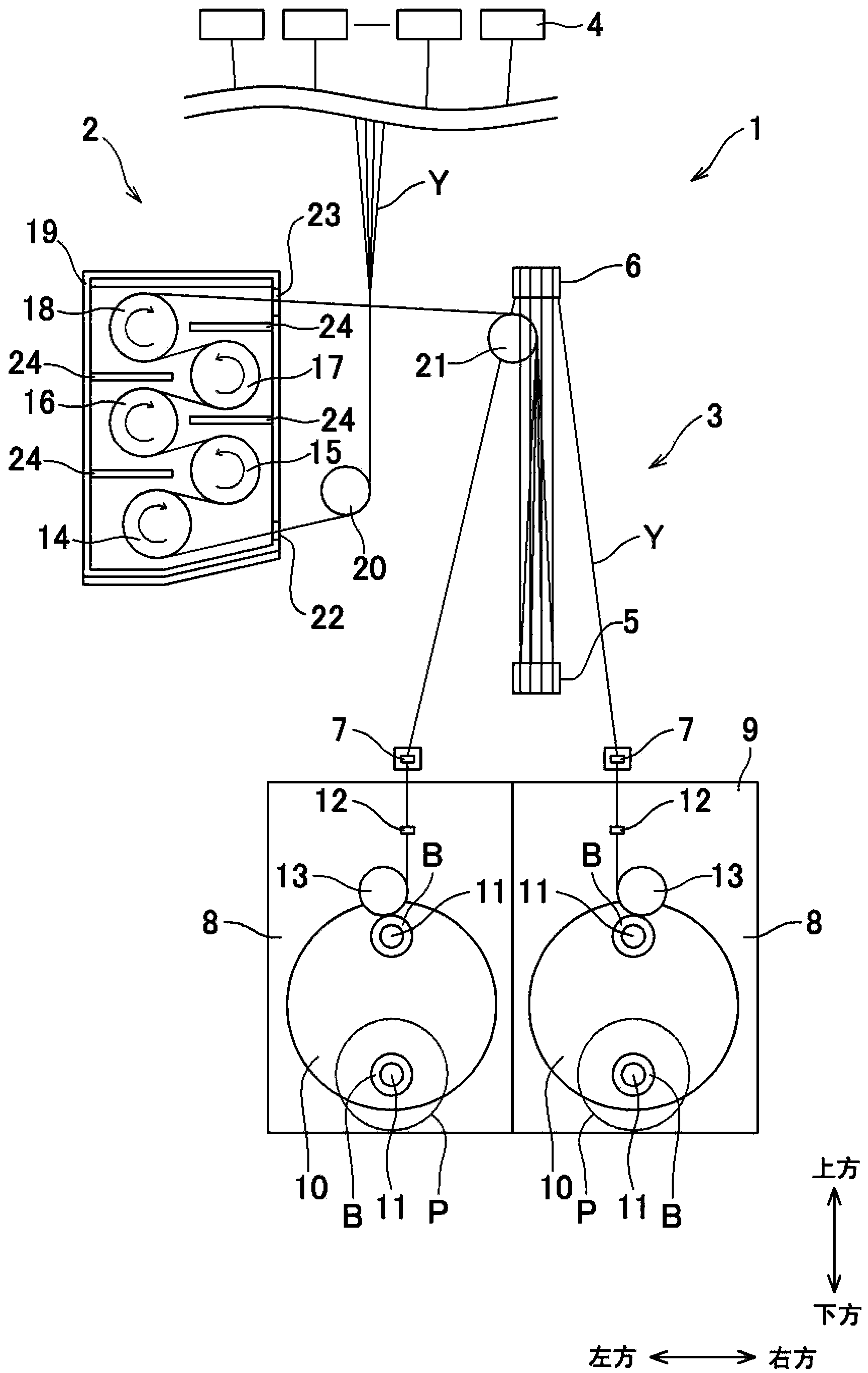
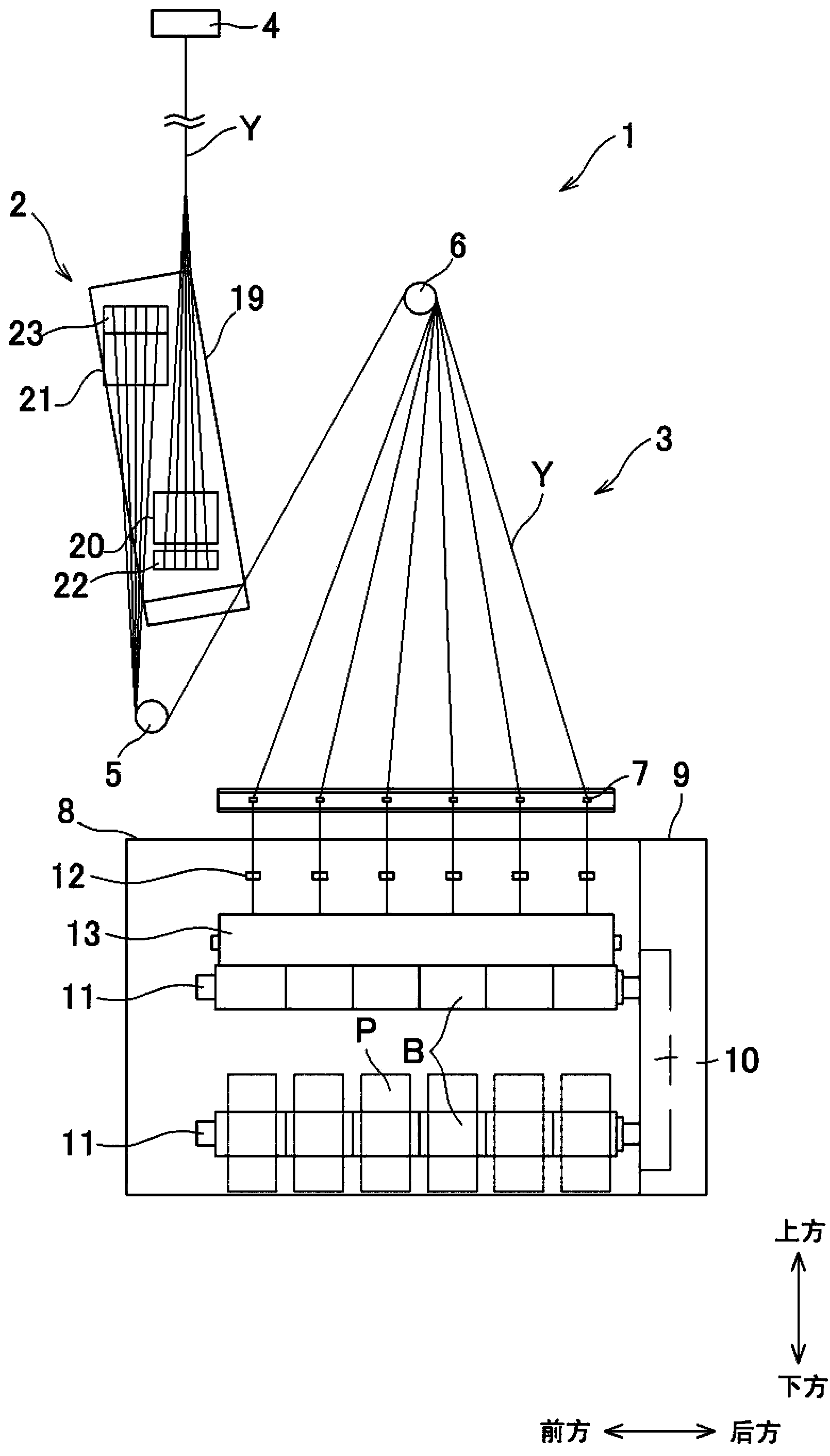
[0038] Embodiments of the present invention will be described below. figure 1 It is a front view showing the structure of the spinning take-up machine provided with the spinning drawing device according to the embodiment of the present invention. figure 2 It is a side view of the spinning take-off machine. Below, with figure 1 as well as figure 2 The directions shown in are described as the up-down direction, the left-right direction, and the front-rear direction. Such as figure 1 as well as figure 2 As shown, the spinning take-up machine 1 includes a spinning drawing device 2 and a yarn winding device 3 . The spinning tractor 1 draws a plurality of yarns Y spun from the spinning device 4 located above and supplied continuously by using the spinning drawing device 2 , and conveys them to the yarn winding device 3 , and the yarn Y is drawn by the yarn winding device 3 . A plurality of threads Y are wound up. The yarn Y is, for example, a polyester fiber that needs to ...


PUM


Abstract

A spun yarn drawing apparatus is disclosed, which is capable of inhibiting swinging of a yarn which is located between two rollers and does not contact with the rollers. The spun yarn drawing apparatus (2) includes godet rollers (14 to 18). The rotating directions of the adjacent two godet rollers in the advancing direction of the yarn (Y) are opposite. Each of the multiple godet rollers (14 to 18) is wound and hung with the yarn (Y) along the rotating direction at a winding angle of 360 degrees or lower. Among the multiple godet rollers (14 to 18), a non-contact length (Lf) of the yarn between the adjacent two godet rollers in the advancing direction of the yarn (Y) is shorther than a contact length (Lc) of the yarn (Y) with respect to each of the adjacent two godet rollers in the advancing direction of the yarn (Y).

Description

technical field [0001] The present invention relates to a spinning and drawing device for drawing a yarn spun from a spinning device. Background technique [0002] There is known a spinning take-up machine provided with a spinning drawing device, a yarn winding device, etc., and the above spinning drawing device is equipped with multiple devices for stretching and thermally fixing yarns such as polyester spun from the spinning device. The above-mentioned yarn winding device winds the yarn stretched by the spinning and drawing device to form a package. [0003] In Patent Document 1 figure 1 In the spinning and drawing device described, two preheating rolls for preheating the yarn before drawing are arranged in a vertical direction, and heat fixing rollers for thermally fixing the drawn yarn are arranged. The two rollers are arranged in an up and down direction. The two rolls for preheating and the two rolls for heat fixing are arranged side by side in the left-right direct...

Claims


Application Information

Patent Timeline
IPC IPC(8): D02J1/22D02J13/00
CPCD01D5/16D02J1/225D01D10/02D04H13/005
Inventor 桥本欣三杉山研志
Owner TMT MACHINERY INC
Why Eureka
Try Eureka